 Facebook
 Google
 GitHub
 Linkedin
Digital Phase Modulation: BPSK, QPSK, DQPSK
In the previous page, we saw that we can use discrete variations in a carrier’s amplitude or frequency as a way of representing ones and zeros. It should come as no surprise that we can also represent digital data using phase; this technique is called phase shift keying (PSK).
Binary Phase Shift Keying
The most straightforward type of PSK is called binary phase shift keying (BPSK), where “binary” refers to the use of two phase offsets (one for logic high, one for logic low).
We can intuitively recognize that the system will be more robust if there is greater separation between these two phases—of course it would be difficult for a receiver to distinguish between a symbol with a phase offset of 90° and a symbol with a phase offset of 91°. We only have 360° of phase to work with, so the maximum difference between the logic-high and logic-low phases is 180°. But we know that shifting a sinusoid by 180° is the same as inverting it; thus, we can think of BPSK as simply inverting the carrier in response to one logic state and leaving it alone in response to the other logic state.
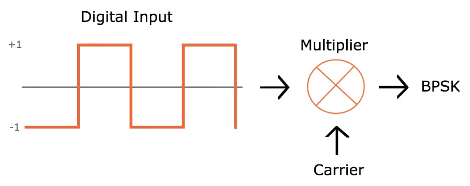
To take this a step further, we know that multiplying a sinusoid by negative one is the same as inverting it. This leads to the possibility of implementing BPSK using the following basic hardware configuration:
However, this scheme could easily result in high-slope transitions in the carrier waveform: if the transition between logic states occurs when the carrier is at its maximum value, the carrier voltage has to rapidly move to the minimum voltage.
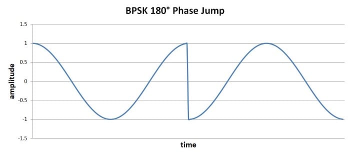
High-slope events such as these are undesirable because they generate higher-frequency energy that could interfere with other RF signals. Also, amplifiers have limited ability to produce high-slope changes in output voltage.
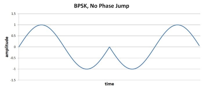
If we refine the above implementation with two additional features, we can ensure smooth transitions between symbols. First, we need to ensure that the digital bit period is equal to one or more complete carrier cycles. Second, we need to synchronize the digital transitions with the carrier waveform. With these improvements, we could design the system such that the 180° phase change occurs when the carrier signal is at (or very near) the zero-crossing.
QPSK
BPSK transfers one bit per symbol, which is what we’re accustomed to so far. Everything we’ve discussed with regard to digital modulation has assumed that the carrier signal is modified according to whether a digital voltage is logic low or logic high, and the receiver constructs digital data by interpreting each symbol as either a 0 or a 1.
Before we discuss quadrature phase shift keying (QPSK), we need to introduce the following important concept: There is no reason why one symbol can transfer only one bit. It’s true that the world of digital electronics is built around circuitry in which the voltage is at one extreme or the other, such that the voltage always represents one digital bit. But RF is not digital; rather, we’re using analog waveforms to transfer digital data, and it is perfectly acceptable to design a system in which the analog waveforms are encoded and interpreted in a way that allows one symbol to represent two (or more) bits.
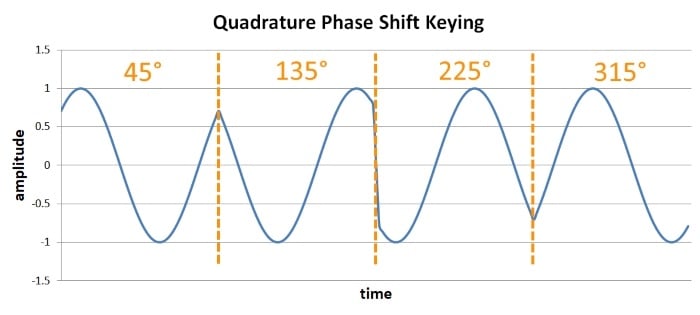
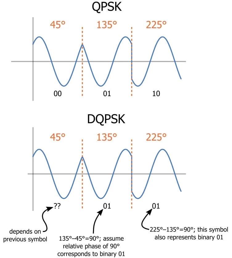
QPSK is a modulation scheme that allows one symbol to transfer two bits of data. There are four possible two-bit numbers (00, 01, 10, 11), and consequently we need four phase offsets. Again, we want maximum separation between the phase options, which in this case is 90°.
The advantage is higher data rate: if we maintain the same symbol period, we can double the rate at which data is moved from transmitter to receiver. The downside is system complexity. (You might think that QPSK is also significantly more susceptible to bit errors than BPSK, since there is less separation between the possible phase values. This is a reasonable assumption, but if you go through the math it turns out that the error probabilities are actually very similar.)
Variants
QPSK is, overall, an effective modulation scheme. But it can be improved.
Phase Jumps
Standard QPSK guarantees that high-slope symbol-to-symbol transitions will occur; because the phase jumps can be ±90°, we can’t use the approach described for the 180° phase jumps produced by BPSK modulation.
This problem can be mitigated by using one of two QPSK variants. Offset QPSK, which involves adding a delay to one of two digital data streams used in the modulation process, reduces the maximum phase jump to 90°. Another option is π/4-QPSK, which reduces the maximum phase jump to 135°. Offset QPSK is thus superior with respect to reducing phase discontinuities, but π/4-QPSK is advantageous because it is compatible with differential encoding (discussed in the next subsection).
Another way to deal with symbol-to-symbol discontinuities is to implement additional signal processing that creates smoother transitions between symbols. This approach is incorporated into a modulation scheme called minimum shift keying (MSK), and there is also an improvement on MSK known as Gaussian MSK.
Differential Encoding
Another difficulty is that demodulation with PSK waveforms is more difficult than with FSK waveforms. Frequency is “absolute” in the sense that frequency changes can always be interpreted by analyzing the signal variations with respect to time. Phase, however, is relative in the sense that it has no universal reference—the transmitter generates the phase variations with reference to a point in time, and the receiver might interpret the phase variations with reference to a separate point in time.
The practical manifestation of this is the following: If there are differences between the phase (or frequency) of the oscillators used for modulation and demodulation, PSK becomes unreliable. And we have to assume that there will be phase differences (unless the receiver incorporates carrier-recovery circuitry).
Differential QPSK (DQPSK) is a variant that is compatible with noncoherent receivers (i.e., receivers that don’t synchronize the demodulation oscillator with the modulation oscillator). Differential QPSK encodes data by producing a certain phase shift relative to the preceding symbol. By using the phase of the preceding symbol in this way, the demodulation circuitry analyzes the phase of a symbol using a reference that is common to the receiver and the transmitter.
Summary
- Binary phase shift keying is a straightforward modulation scheme that can transfer one bit per symbol.
- Quadrature phase shift keying is more complex but doubles the data rate (or achieves the same data rate with half the bandwidth).
- Offset QPSK, π/4-QPSK, and minimum shift keying are modulation schemes that mitigate the effects of high-slope symbol-to-symbol voltage changes.
- Differential QPSK uses the phase difference between adjacent symbols to avoid problems associated with a lack of phase synchronization between the transmitter and receiver.


