Facebook
 Google
 GitHub
 Linkedin
Voltage-to-Current Signal Conversion
In instrumentation circuitry, DC signals are often used as analog representations of physical measurements such as temperature, pressure, flow, weight, and motion. Most commonly, DC current signals are used in preference to DC voltage signals, because current signals are exactly equal in magnitude throughout the series circuit loop carrying current from the source (measuring device) to the load (indicator, recorder, or controller), whereas voltage signals in a parallel circuit may vary from one end to the other due to resistive wire losses. Furthermore, current-sensing instruments typically have low impedances (while voltage-sensing instruments have high impedances), which gives current-sensing instruments greater electrical noise immunity.
In order to use current as an analog representation of a physical quantity, we have to have some way of generating a precise amount of current within the signal circuit. But how do we generate a precise current signal when we might not know the resistance of the loop? The answer is to use an amplifier designed to hold current to a prescribed value, applying as much or as little voltage as necessary to the load circuit to maintain that value. Such an amplifier performs the function of a current source. An op-amp with negative feedback is a perfect candidate for such a task:
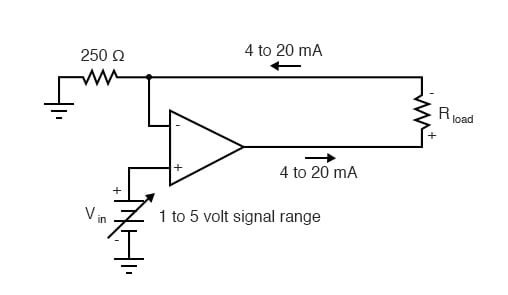
The input voltage to this circuit is assumed to be coming from some type of physical transducer/amplifier arrangement, calibrated to produce 1 volt at 0 percent of physical measurement, and 5 volts at 100 percent of physical measurement. The standard analog current signal range is 4 mA to 20 mA, signifying 0% to 100% of measurement range, respectively. At 5 volts input, the 250 Ω (precision) resistor will have 5 volts applied across it, resulting in 20 mA of current in the large loop circuit (with Rload). It does not matter what resistance value Rload is, or how much wire resistance is present in that large loop, so long as the op-amp has a high enough power supply voltage to output the voltage necessary to get 20 mA flowing through Rload. The 250 Ω resistor establishes the relationship between input voltage and output current, in this case creating the equivalence of 1-5 V in / 4-20 mA out. If we were converting the 1-5 volt input signal to a 10-50 mA output signal (an older, obsolete instrumentation standard for industry), we’d use a 100 Ω precision resistor instead.
Another name for this circuit is transconductance amplifier. In electronics, transconductance is the mathematical ratio of current change divided by voltage change (ΔI / Δ V), and it is measured in the unit of Siemens, the same unit used to express conductance (the mathematical reciprocal of resistance: current/voltage). In this circuit, the transconductance ratio is fixed by the value of the 250 Ω resistor, giving a linear current-out/voltage-in relationship.
REVIEW:
- In industry, DC current signals are often used in preference to DC voltage signals as analog representations of physical quantities. Current in a series circuit is absolutely equal at all points in that circuit regardless of wiring resistance, whereas voltage in a parallel-connected circuit may vary from end to end because of wire resistance, making current-signaling more accurate from the “transmitting” to the “receiving” instrument.
- Voltage signals are relatively easy to produce directly from transducer devices, whereas accurate current signals are not. Op-amps can be used to “convert” a voltage signal into a current signal quite easily. In this mode, the op-amp will output whatever voltage is necessary to maintain current through the signaling circuit at the proper value.
RELATED WORKSHEET: