Facebook
 Google
 GitHub
 Linkedin
An Analogy for Divided Feedback
A helpful analogy for understanding divided feedback amplifier circuits is that of a mechanical lever, with relative motion of the lever’s ends representing change in input and output voltages, and the fulcrum (pivot point) representing the location of the ground point, real or virtual.
Take for example the following noninverting op-amp circuit. We know from the prior section that the voltage gain of a noninverting amplifier configuration can never be less than unity (1). If we draw a lever diagram next to the amplifier schematic, with the distance between fulcrum and lever ends representative of resistor values, the motion of the lever will signify changes in voltage at the input and output terminals of the amplifier:
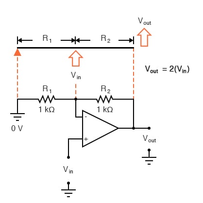
Physicists call this type of lever, with the input force (effort) applied between the fulcrum and output (load), a third-class lever. It is characterized by an output displacement (motion) at least as large than the input displacement—a “gain” of at least 1—and in the same direction. Applying a positive input voltage to this op-amp circuit is analogous to displacing the “input” point on the lever upward:
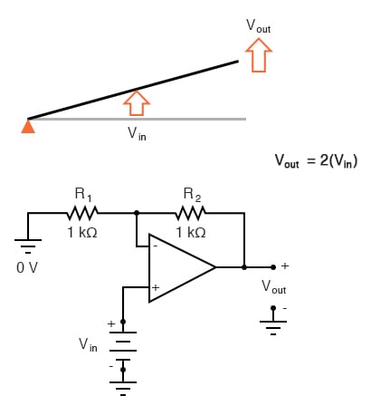
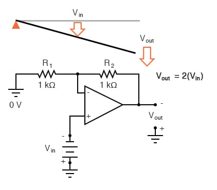
Due to the displacement-amplifying characteristics of the lever, the “output” point will move twice as far as the “input” point, and in the same direction. In the electronic circuit, the output voltage will equal twice the input, with the same polarity. Applying a negative input voltage is analogous to moving the lever downward from its level “zero” position, resulting in an amplified output displacement that is also negative:
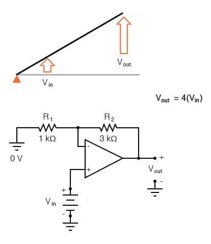
If we alter the resistor ratio R2/R1, we change the gain of the op-amp circuit. In lever terms, this means moving the input point in relation to the fulcrum and lever end, which similarly changes the displacement “gain” of the machine:
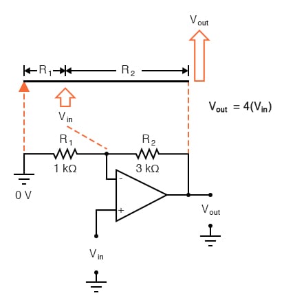
Now, any input signal will become amplified by a factor of four instead of by a factor of two:
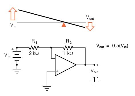
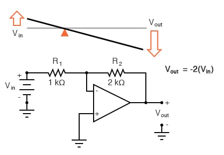
Inverting op-amp circuits may be modeled using the lever analogy as well. With the inverting configuration, the ground point of the feedback voltage divider is the op-amp’s inverting input with the input to the left and the output to the right. This is mechanically equivalent to a first-class lever, where the input force (effort) is on the opposite side of the fulcrum from the output (load):
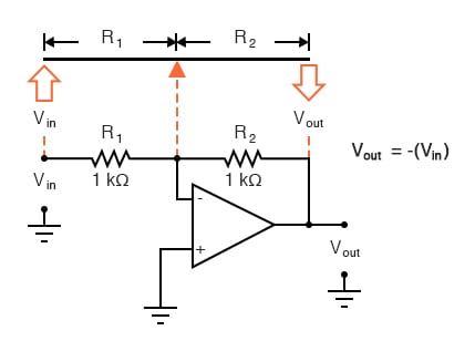
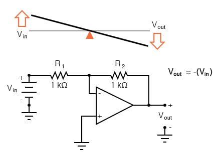
With equal-value resistors (equal-lengths of lever on each side of the fulcrum), the output voltage (displacement) will be equal in magnitude to the input voltage (displacement), but of the opposite polarity (direction). A positive input results in a negative output:
Changing the resistor ratio R2/R1 changes the gain of the amplifier circuit, just as changing the fulcrum position on the lever changes its mechanical displacement “gain.” Consider the following example, where R2 is made twice as large as R1:
With the inverting amplifier configuration, though, gains of less than 1 are possible, just as with first-class levers. Reversing R2 and R1 values is analogous to moving the fulcrum to its complementary position on the lever: one-third of the way from the output end. There, the output displacement will be one-half the input displacement: