 Facebook
 Google
 GitHub
 Linkedin
Op-Amps as Low-Pass and High-Pass Active Filters
First-order low-pass and high-pass filters require nothing more than resistors and capacitors. These passive filters are easy to design and analyze, and they offer performance that is adequate in many applications.
When system requirements cannot be met by a first-order filter, the designer must consider a second-order (or third-order, or fourth-order...) filter.
Higher-order filters can be achieved by taking advantage of the resonance that results from the interaction of capacitance and inductance. However, engineers often try to avoid the use of inductors; relative to resistors and capacitors, they are larger, more susceptible to EMI, more likely to generate problematic EMI, and less compatible with integrated-circuit techniques.
Inductor Replacement
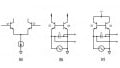
It turns out that the effect of inductance can be duplicated by combining an op-amp with clever circuit design. The following diagram shows an op-amp-based circuit that functions as an inductor (the inductance is determined by the values of the passive components).
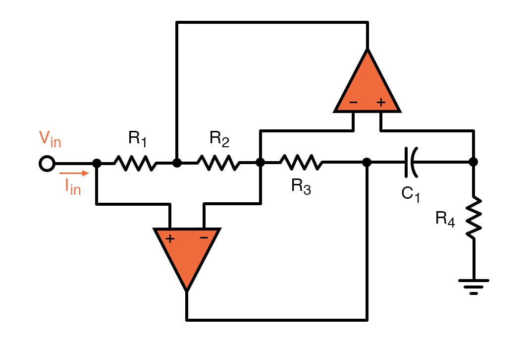
This circuit is an op-amp–RC resonator: it produces resonance using only resistance, capacitance, and amplification. We could use this circuit to replace the inductor in a second-order RLC (resistor-inductor-capacitor) filter, but instead, we’ll look at a simpler and more compact topology known as the Sallen-Key filter.
Second-Order Active Low-Pass Filter
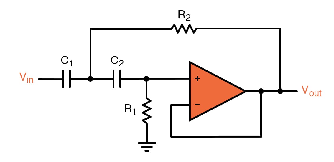
The following schematic is a unity-gain Sallen-Key low-pass filter. As you can see, it requires only one op-amp, two resistors, and two capacitors. We call these filters “active” because they include an amplifying component.

There are two feedback paths, one of which is directed toward the op-amp’s non-inverting input terminal. We’re accustomed to analyzing op-amp circuits that have only negative feedback.
A detailed analysis of the Sallen-Key low-pass filter is not particularly straightforward. Nevertheless, we can acquire a general understanding of the circuit’s operation by performing non-mathematical analysis.
Notice that the passive components resemble a typical second-order RC low-pass filter. The only difference is that C2, instead of creating a high-frequency path to ground, creates a high-frequency path for positive feedback.
This positive feedback allows the filter to overcome the fundamental limitation of the RCRC second-order low-pass filter: even when a buffer is placed between the two RC stages, the filter’s Q factor cannot exceed 0.5. A Q factor of 0.5 is often unacceptably low, and the Sallen-Key architecture overcomes this limitation by using positive feedback to enable higher Q.
The qualitative operation of the unity-gain Sallen-Key low-pass filter becomes clear if you combine the preceding discussion with the fact that the negative-feedback path is a direct connection from the output node to the inverting input terminal:
- If we ignore the positive-feedback path, the circuit is a second-order RC low-pass filter connected to a voltage follower.
- High frequencies are shorted to ground, and low frequencies are passed to the input of the op-amp. In both cases, the op-amp produces a buffered version of the output of the RCRC filter.
- At frequencies near the cutoff frequency, the impedance of the capacitors is comparable to the resistance of the resistors, and the positive-feedback path provided by C2 allows the circuit to generate the higher-Q type of response that we expect from resonance-based filters.
The cutoff frequency of the unity-gain Sallen-Key low-pass filter is given by the following expression:
\[f_C= \frac {1}{2\pi R_1C_1R_2C_2}\]
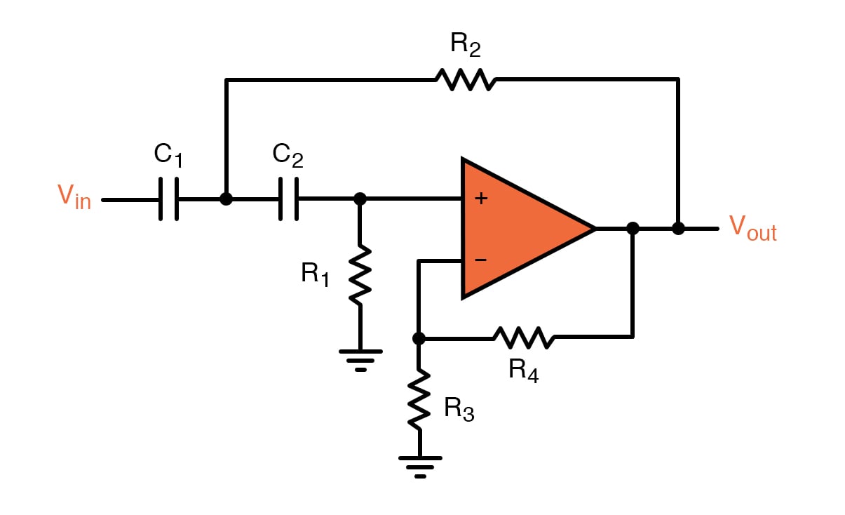
We can create a non-unity-gain active filter by including the familiar resistive divider in the negative-feedback path:

As with the typical op-amp-based non-inverting amplifier, the low-frequency gain of this filter will be
\[K=1+ \frac {R_4}{R_3}\]
Second-Order Active High-Pass Filter
If we swap the resistor and capacitor in an RC low-pass filter, we convert the circuit into a CR high-pass filter. We can then cascade two CR high-pass filters to create a second-order CRCR high-pass filter. If we incorporate this passive configuration into the Sallen-Key topology, we have the following:
This is the Sallen-Key unity-gain high-pass filter. The expression for cutoff frequency does not change, and we use the same technique to incorporate gain:
\[f_C=\frac {1}{2\pi \sqrt{ R_1C_1R_2C_2}}\]
Summary
- Op-amps can be used to create compact, high-performance second-order filters that do not require inductors. An op-amp-based filter is called an active filter.
- The Sallen-Key topology uses positive feedback to overcome the Q-factor limitation exhibited by second-order filters that consist only of resistors and capacitors.
- Active filters can increase the amplitude of a signal in addition to modifying its frequency content. In the Sallen-Key topology, gain is implemented by including a typical resistive divider in the negative-feedback path.


Rob – you said “If we ignore the positive feedback path the circuit is a second-order RC low-pass connected to a voltage follower.”
In what sense are you “ignoring” C2! Removing it? Unless you disconnect the right side of C2, and ground that lead, it is just first order.
Did you not misspeak? —Bernie
Please see my Electronotes EN191, Sect 2-3, pp 29-31 (Dec. 1999) for a complete (and simple) analysis of the Sallen-Key low-pass.
http://electronotes.netfirms.com/EN191.pdf
-Bernie