Facebook
 Google
 GitHub
 Linkedin
The Basics of Electrical Resistance (R)
Video Transcript
In this video tutorial, we'll explore a fundamental electrical property that figures prominently in the analysis and design of electronic systems.
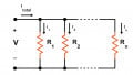
In a functional circuit, there is a relationship between voltage and current. If a voltage source is connected to a component or a network of components, current will flow (Figure 1). The amount of current, however, is not determined solely by the voltage source.
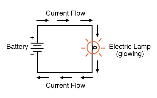
Figure 1. Example of electric current flow in a lamp circuit powered by a battery
The wires and components in the circuit will present some amount of resistance to the movement of electric charge. And this influences the magnitude of the current produced by a given voltage source. Resistance is denoted in ohms and has the symbol of the capital Greek omega (Ω). And this value allows us to quantify opposition to electric current.
All materials except superconductors present some amount of resistance. The terms conductor and insulator do not identify materials that have, respectively, zero resistance and infinite resistance. Rather, they are convenient ways of referring to materials that exhibit very low resistance and very high resistance.
The symbols shown here (Figures 2 and 3) represent resistors in a circuit diagram.
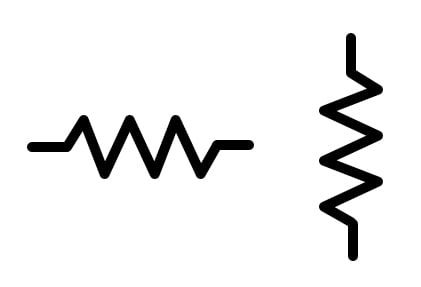
Figure 2. ANSI (US) resistor symbols
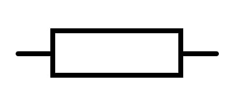
Figure 3. IEC (international) resistor symbol
Sometimes resistance is a nuisance because it reduces the amount of current delivered to the user and dissipates power as unwanted heat. However, resistance plays an essential role in circuit design and is used for such tasks as reducing the amplitude of a signal, establishing the gain of an amplifier circuit, limiting the current through a light-emitting diode, and creating frequency-dependent networks called filters.
The intentional resistance that we incorporate into electronic circuits comes in the form of individual components called resistors.
Parasitic Resistance
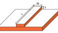
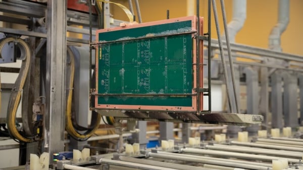
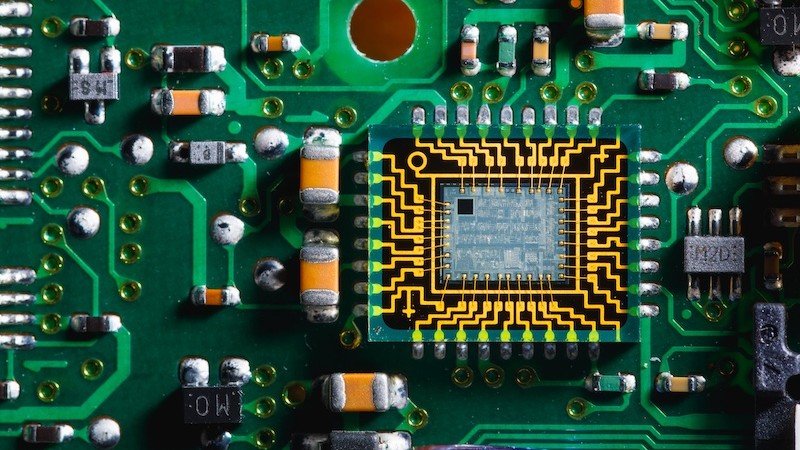
Electrical circuits are filled with resistance that does not originate from resistors’ wires. Printed circuit board traces pins on integrated circuits; leads on capacitors and inductors (Figure 4). When we're working with typical electronic systems, there is no such thing as a perfect conductor. This type of resistance is called parasitic resistance.
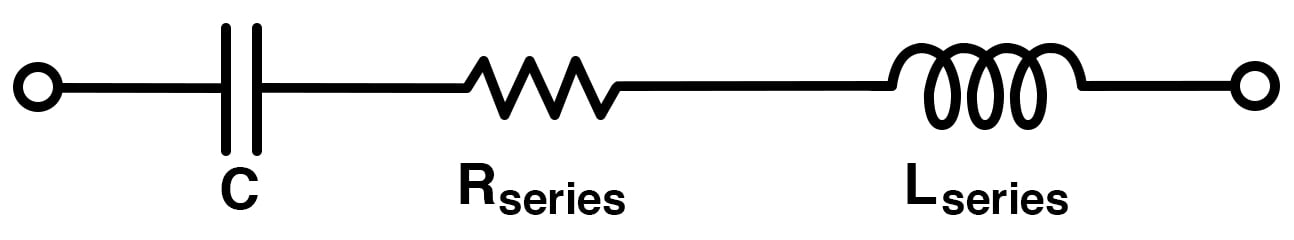
Figure 4. Example of parasitic series resistance in an LC circuit
The degree to which it affects the functionality of a circuit depends on various factors. In many cases, parasitic resistance can be ignored because it will not alter the circuit's functionality in any noticeable way.
Units of Resistance and Conductance
As noted earlier, ohms are the unit of resistance. This quantifies a material's tendency to oppose current. A related unit, siemens (S), quantifies a material's conductance or its tendency to allow the flow of electric current. Ohms quantifies resistance, and siemens quantifies conductance. The two have a reciprocal relationship. Thus a 50 W resistor has a conductance of 1/50 or 0.02 Siemens.
Related Content
Learn more about the fundamentals explained by this video in the resources below.
Textbook:
Resistor Guide:
Projects:
- How to Use an Ohmmeter to Measure Resistance
- Intro Lab - Ohm’s Law
- Intro Lab - Resistor Power Dissipation
Worksheets: