 Facebook
 Google
 GitHub
 Linkedin
The Instrumentation Amplifier
What Is an Instrumentation Amplifier?
An instrumentation amplifier allows an engineer to adjust the gain of an amplifier circuit without having to change more than one resistor value. Compare this to the differential amplifier, which we covered previously, which requires the adjustment of multiple resistor values.
The so-called instrumentation amplifier builds on the last version of the differential amplifier to give us that capability:
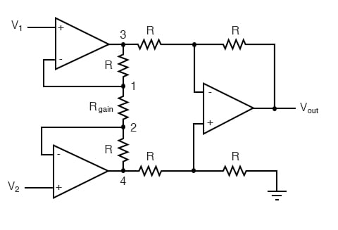
Understanding the Instrumentation Amplifier Circuit
This intimidating circuit is constructed from a buffered differential amplifier stage with three new resistors linking the two buffer circuits together. Consider all resistors to be of equal value except for Rgain.
The negative feedback of the upper-left op-amp causes the voltage at point 1 (top of Rgain) to be equal to V1. Likewise, the voltage at point 2 (bottom of Rgain) is held to a value equal to V2. This establishes a voltage drop across Rgain equal to the voltage difference between V1 and V2. That voltage drop causes a current through Rgain, and since the feedback loops of the two input op-amps draw no current, that same amount of current through Rgain must be going through the two “R” resistors above and below it.
This produces a voltage drop between points 3 and 4 equal to:
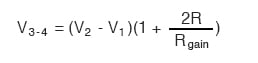
The regular differential amplifier on the right-hand side of the circuit then takes this voltage drop between points 3 and 4 and amplifies it by a gain of 1 (assuming again that all “R” resistors are of equal value).
Advantages of the Instrumentation Amplifier
Though this looks like a cumbersome way to build a differential amplifier, it has the distinct advantages of possessing extremely high input impedances on the V1 and V2 inputs (because they connect straight into the noninverting inputs of their respective op-amps), and adjustable gain that can be set by a single resistor.
Manipulating the above formula a bit, we have a general expression for overall voltage gain in the instrumentation amplifier:
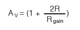
Though it may not be obvious by looking at the schematic, we can change the differential gain of the instrumentation amplifier simply by changing the value of one resistor: Rgain.
Yes, we could still change the overall gain by changing the values of some of the other resistors, but this would necessitate balanced resistor value changes for the circuit to remain symmetrical. Please note that the lowest gain possible with the above circuit is obtained with Rgain completely open (infinite resistance), and that gain value is 1.
REVIEW:
- An instrumentation amplifier is a differential op-amp circuit providing high input impedances with ease of gain adjustment through the variation of a single resistor.
RELATED WORKSHEET:


It seems to me that the power supply is missing on the circuit image.