Facebook
 Google
 GitHub
 Linkedin
Digital Circuits
Performance-Based Assessments for Digital Circuit Competencies
43 questions By Tony R. Kuphaldt
-
Question 34 of 43
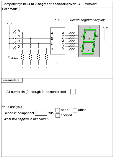
Reveal answerUse circuit simulation software to verify your predicted and actual truth tables.
Notes:Students are left on their own to figure out what they must do with the other inputs (lamp test, BI, RBI, etc.) to make the decoder/driver chip function properly.
-
Question 35 of 43
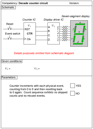
Reveal answerUse circuit simulation software to verify your predicted and measured parameter values.
Notes:I have purposely left the details of the schematic diagram vague, so that students must do a lot of datasheet research on their own to figure out how to make an event counter circuit. You may choose to give your students part numbers for the integrated circuits, or choose not to, depending on how capable your students are. The point is, they must figure out how to make the ICs work based on what they read from the manufacturer.
Something else students will probably have to do is de-bounce the event switch. Some event switches are inherently bounce-less, while others are definitely not. Switch debouncing is something your students need to learn about and integrate into this circuit.
An extension of this exercise is to incorporate troubleshooting questions. Whether using this exercise as a performance assessment or simply as a concept-building lab, you might want to follow up your students’ results by asking them to predict the consequences of certain circuit faults.
-
Question 36 of 43

Reveal answerUse circuit simulation software to verify your predicted and actual truth tables.
Notes:Students are to research the datasheet for their particular IC and figure out from that what connections and timing sequences they need to make the circuit perform as requested. It is very important for students to learn to interpret manufacturers’ datasheets!
I recommend a slow clock frequency (1 Hz or so) to allow for easy viewing of the shift patterns. To conserve the number of necessary input switches, I allow students to hard-wire the data inputs (D0 through D3). This means they only need switches to control the mode of the shift register (parallel load, shift right, shift left, and shift inhibit).