Facebook
 Google
 GitHub
 Linkedin
AC Electric Circuits
Resonance
26 questions By Tony R. Kuphaldt
-
Question 19 of 26
Shown here are two frequency response plots (known as Bode plots) for a pair of series resonant circuits. Each circuit has the same inductance and capacitance values, but different resistance values. The “output” is voltage measured across the resistor of each circuit:
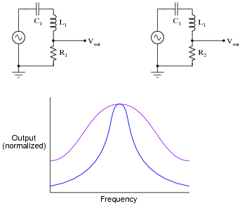
Which one of these plots represents the response of the circuit with the greatest Q, or quality factor?
Reveal answerThe steeper plot corresponds to the circuit with the greatest Q.
Follow-up question: assuming both the inductance and the capacitance values are the same in these two resonant circuits, explain which circuit has the greatest resistance (R1 or R2).
Challenge question: what does the word “normalized” mean with respect to the vertical axis scale of the Bode plot?
Notes:When your students study resonant filter circuits, they will better understand the importance of Q. For now, though, it is enough that they comprehend the basic notion of how Q impacts the voltage dropped by any one component in a series resonant circuit across a range of frequencies.
-
Question 20 of 26
The Q, or quality factor, of an inductor circuit is defined by the following equation, where Xs is the series inductive reactance and Rs is the series resistance:
Q = Xs RsWe also know that we may convert between series and parallel equivalent AC networks with the following conversion equations:
Rs Rp = Z2 Xs Xp = Z2 
Series and parallel LR networks, if truly equivalent, should share the same Q factor as well as sharing the same impedance. Develop an equation that solves for the Q factor of a parallel LR circuit.
Reveal answerQ = Rp XpFollow-up question: what condition gives the greatest value for Q, a low parallel resistance or a high parallel resistance? Contrast this against the effects of low versus high resistance in a series LR circuit, and explain both scenarios.
Notes:This is primarily an exercise in algebraic substitution, but it also challenges students to think deeply about the nature of Q and what it means, especially in the follow-up question.
-
Question 21 of 26
There is a direct, mathematical relationship between bandwidth, resonant frequency, and Q in a resonant filter circuit, but imagine for a moment that you forgot exactly what that formula was. You think it must be one of these two, but you are not sure which:
Bandwidth = Q fr(or possibly) Bandwidth = fr QBased on your conceptual knowledge of how a circuit’s quality factor affects its frequency response, determine which of these formulae must be incorrect. In other words, demonstrate which of these must be correct rather than simply looking up the correct formula in a reference book.
Reveal answerHint: the greater the value of Q, the less bandwidth a resonant circuit will have.
Notes:The purpose of this question is not necessarily to get students to look this formula up in a book, but rather to develop their qualitative reasoning and critical thinking skills. Forgetting the exact form of an equation is not a rare event, and it pays to be able to select between different forms based on a conceptual understanding of what the formula is supposed to predict.
Note that the question asks students to identify the wrong formula, and not to tell which one is right. If all we have are these to formulae to choose from, and a memory too weak to confidently recall the correct form, the best that logic can do is eliminate the wrong formula. The formula making the most sense according to our qualitative analysis may or may not be precisely right, because we could very well be forgetting a multiplicative constant (such as 2 π).