Facebook
 Google
 GitHub
 Linkedin
AC Electric Circuits
Resonance
26 questions By Tony R. Kuphaldt
-
Question 22 of 26
Suppose you have a 110 mH inductor, and wish to combine it with a capacitor to form a band-stop filter with a “notch” frequency of 1 kHz. Draw a schematic diagram showing what the circuit would look like (complete with input and output terminals) and calculate the necessary capacitor size to do this, showing the equation you used to solve for this value. Also, calculate the bandwidth of this notch filter, assuming the inductor has an internal resistance of 20 ohms, and that there is negligible resistance in the rest of the circuit.
Reveal answer
The bandwidth of this 1 kHz notch filter is approximately 29 Hz.
Follow-up question: suppose you looked around but could not find a capacitor with a value of 0.23 μF. What could you do to obtain this exact capacitance value? Be as specific and as practical as you can in your answer!
Notes:In my answer I used the series-resonant formula \(f_{r}=\frac{1}{2 \pi \sqrt{LC}}\), since the series formula gives good approximations for parallel resonant circuits with Q factors in excess of 10.
The follow-up question is very practical, since it is often common to need a component value that is non-standard. Lest any of your students suggest obtaining a variable capacitor for this task, remind them that variable capacitors are typically rated in the pico-Farad range, and would be much too small for this application.
-
Question 23 of 26
Shown here are two frequency response plots (known as Bode plots) for a pair of series resonant circuits with the same resonant frequency. The “output” is voltage measured across the resistor of each circuit:
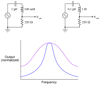
Determine which plot is associated with which circuit, and explain your answer.
Reveal answerThe steeper plot corresponds to the circuit with the greatest \(\frac{L}{C}\) ratio.
Follow-up question: what kind of instrument(s) would you use to plot the response of a real resonant circuit in a lab environment? Would an oscilloscope be helpful with this task? Why or why not?
Notes:Discuss with your students why the LC circuit with the greatest L/C ratio has the steeper response, in terms of reactances of the respective components at the resonant frequency.
The purpose of this question is to get students to realize that not all resonant circuits with identical resonant frequencies are alike! Even with ideal components (no parasitic effects), the frequency response of a simple LC circuit varies with the particular choice of component values. This is not obvious from inspection of the resonant frequency formula:
fr = 1 2 π √ LC -
Question 24 of 26
Given the unavoidable presence of parasitic inductance and/or capacitance in any electronic component, what does this mean in terms of resonance for single components in AC circuits?
Reveal answerParasitic reactance means that any single component is theoretically capable of resonance, all on its own!
Follow-up question: at what frequency would you expect a component to self-resonate? Would this be a very low frequency, a very high frequency, or a frequency within the circuit’s normal operating range? Explain your answer.
Notes:This question grew out of several years’ worth of observations, where students would discover self-resonant effects in large ( > 1 Henry) inductors at modest frequencies. Being a recurring theme, I thought it prudent to include this question within my basic electronics curriculum.
One component that tends to be more immune to self-resonance than others is the lowly resistor, especially resistors of large value. Ask your students why they think this might be. A mechanical analogy to self-resonance is the natural frequency of vibration for an object, given the unavoidable presence of both elasticity and mass in any object. The mechanical systems most immune to vibratory resonance, though, are those with a high degree of intrinsic friction.