 Facebook
 Google
 GitHub
 Linkedin
Precisely Capture Servo Motor Position Using a High-Speed Simultaneous Sampling ADC
Autonomous drones and robots utilize small motors. These fast-spinning mini motors require miniature encoders and IC package sizes. This article shows how an optical sinusoidal encoder provides a higher resolution and increased speeds with a 2x3 mm dual simultaneous-sampling SAR-ADC.
From the production floor to autonomous drones, robots are all around us, utilizing fast, high-resolution, smaller motors. This fast-spinning, mini motor requires miniature encoders and miniaturized IC package sizes.
All these design specifications seem to be mutually exclusive; for instance, faster signal encoder conversions usually compromise Heading 5the resolution. This system design is challenging for designers as the swiftly spinning motors continually require complementary sampling speeds. The essential tasks robots perform are movement and sensing, and having analog-to-digital converters (ADCs) in the encoder with high-resolution and fast conversion rates is at the heart of its function.
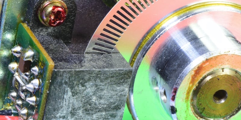
Figure 1. Rotary motor encoder sensing notches on the wheel.
This article briefly discusses the issues associated with achieving a small, high precision motor encoder for the faster spinning motors. It introduces an encoder with a dual simultaneous-sampling, successive-approximation-register analog-to-digital-converter (SAR-ADC), and how to take advantage of the internal reference and dual simultaneous-sampling input stage.
Motor Encoder
An incremental encoder is an electromechanical motion detector. It has two output signals, A and B, which indicate the direction of movement and distance traveled. Together, these signals determine direction and velocity. The third signal from the encoder determines the motor’s position.
The two types of incremental encoders are linear and rotary. Linear encoders move items in a single dimension or direction and convert linear positions into electronic signals. Rotary encoders move items around an axis and convert the rotary positions or angles into electronic signals. Each output signal corresponds to a constant angle change of the shaft. Motors often use incremental rotary encoders to perform direction, velocity, and position tracking (Figure 2).
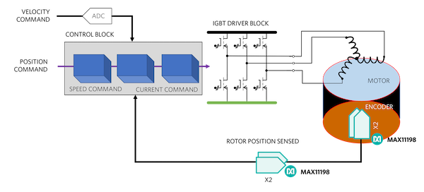
Figure 2. A motor effectively utilizes a rotary encoder, that quantifies the motor’s direction, velocity, and position.
The two common types of incremental rotary encoders have digital or sinusoidal signal outputs. Digital incremental rotary encoders have patterns on the disk that outputs a 50% duty cycle, high or low digital signal.
Digital Encoder
An optical digital encoder transmits light through the slots of the motor wheel. The optical receiver registers a high digital output when the light appears and low digital out in the darkness (Figure 3).
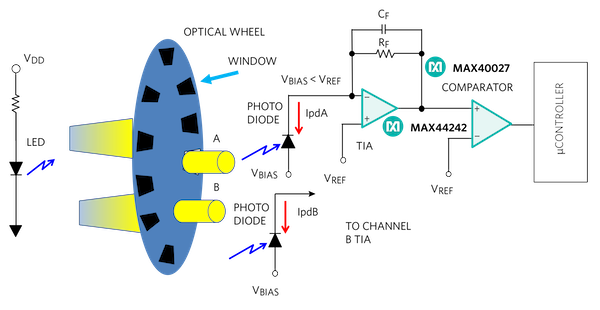
Figure 3. Optical digital encoder showing Channel A and Channel B, where Channel B duplicates the Channel A signal chain.
On the other side of the motor wheel, a photodiode (Figure 3) and a transimpedance amplifier sense the digital light pulse. The transimpedance amplifier’s interface complements the photodiode with low input 0.5 pA input bias currents and low 5 nV/√Hz @ 1 kHz noise. Signals in channel A and B go through their respective comparators to the microcontroller, that captures the final digital events. The key to the Channel A and B arrangement is that the microcontroller simultaneously latches these two signals.
It is important to create a stable TIA circuit in Figure 3 to eliminate uncertainty. The feedback resistor (RF) and feedback capacitor (CF) interacts with the amplifiers input capacitance (CDifferential + CCommon-Mode = CAMP) and the photodiode parasitic capacitance (CPD). The most efficient TIA circuit is one with a 65° phase margin, Butterworth response. This phase margin magnitude produces a 5% step response overshoot. Equation 1 shows the TIA calculation that emulates a Butterworth response.

where fGBW is the gain-bandwidth-product of the unity gain stable amplifier and CRF is the parasitic RF capacitance.
Equation 1 allows the circuit designer to vary the amplifier bandwidth/input capacitance as well as the feedback resistor value. For more TIA stability information, see TIA Fundamentals: The Noise Transfer Function Part 4.
In Figure 3, the two optical channels, A and B, collect the motor’s direction and velocity data. To measure the direction, the location of the optics and the distance between each optical wheel window establishes a 90-degree phase between the A and B square waves. The motor direction relates to the sign of the phase angle. The phase difference is positive if the rising edge of the A channel precedes the rising edge of the B channel (Figure 4a).
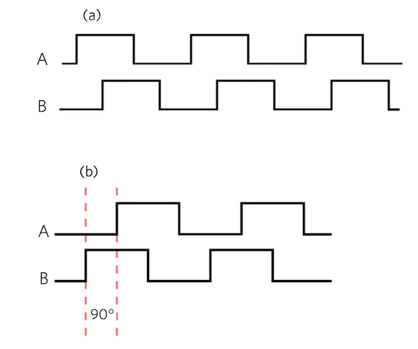
Figure 4. The encoder simultaneously captures the digital Channel A and Channel B signals.
As in Figure 4.b, the phase difference is negative if the rising edge of the A channel follows the rising edge of the B channel the rising edge.
The frequency of either A or B square waves determines the motor speed.
The mechanics of Figure 3 produce multiple periods in one motor shaft revolution. Encoder manufacturers produce incremental digital rotary encoders (and incremental sine/cosine rotary encoders) with from 50 up to 5,000 periods per revolution.
In addition to the digital signal, there is also a reference mark on the wheel to determine the motor’s rotary position. Design engineers refer to the reference mark as the 0° angle of 360-degree motor wheel circumference. The digital pulse reference mark count determines the motor’s exact rotary position.
Sinusoidal Encoder
An incremental sinusoidal encoder also provides the direction of movement and distance traveled with a pair of quadrature sine and cosine signals. Instead of digital outputs, the outputs of this encoder are sine and cosine waves providing higher resolution at higher speeds for movement and distance.
This type of encoder has three signals: Sine, Cosine, and a reference pulse (Figure 5).
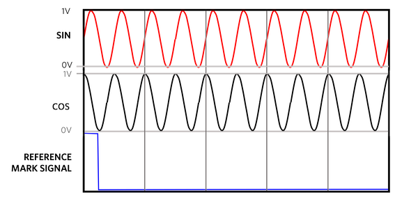
Figure 5. Sinusoidal signals comprised of sine and cosine waves where the encoder performs simultaneous samples of both signals.
The analog sinusoidal encoder requires an all-analog signal chain. The extraction of reliable position and speed information from the sinusoidal encoder signals has a certain amount of analog signal pre-conditioning. At the first input of the ADC there is the conversion of SIN and COS signals (typically 1Vpp input signal range) to a differential signal. The differential signal ensures maximum noise immunity and offers the opportunity to appropriately amplify and level shift the resultant single-ended SIN and COS signals in preparation for Analog to Digital Converter (ADC) input stage.
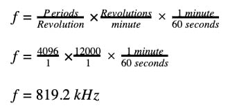
Each revolution has multiple signal periods. The resulting sine/cosine frequency depends on the number of signal periods and the number of revolutions per minute. For example, the equations below show the sine/cosine frequency of an encoder that has 4,096 periods in one revolution and a motor spinning at 1,400 revolutions per minute (Equation 2):
For this example, the signal-chain solution bandwidth is at least 1600 kHz. This closed-loop control system requires an extremely low zero latency, which a dual simultaneously sampling ADC provides. The encoder output is 1 VP-P (typical), with differential sine and cosine output signals.
The analog signal-chain requirements are:
- Two simultaneously-sampling ADCs: ADC1 provides the sine output, and ADC2 provides the cosine output.
- No system latency: preferably a SAR (successive-approximation register) converter (versus ΔƩ or pipeline converter)
- More than 800 kHz of bandwidth, thus an ADC that converts at a greater than 1600 ksps per channel minimum rate to satisfy the Nyquist theorem.
- 1-VP-P differential input.
The optimum solution is a dual simultaneous sampling SAR ADC (Figure 5).
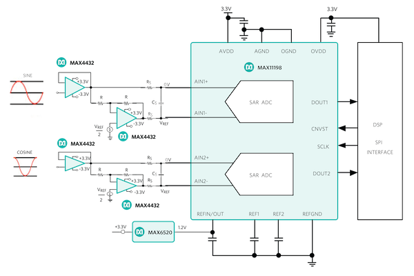
Figure 6. A dual, simultaneous sampling 2 Msps ADC with an input frequency of 800 kHz determines a motor’s direction and velocity with motor coil sinusoidal signals.
In Figure 6, two single-supply op amps convert the input signals to a differential signal to drive the fully differential ADC. The ADC’s external 1.2V voltage reference provides a well-regulated reference point for the 16-bit conversions. With two simultaneously-sampling channels, the ADC’s 2-Msps per channel output data rate meets the specified requirements.
In this example, 2mm x 3mm TDFN MAX11198 is a 16-bit ADC and the sinusoidal incremental rotary encoder has 4,096 periods in one revolution. The calculation for the total number of measurement steps is (Equation 3):

This approach gives the designer 16-bit ADC resolution and 4096 periods (4096 = 212 ) for 16 + 12 or 28-bits of resolution or a rotary position accuracy within 1.341 × μ degrees.
Conclusion
This article briefly discusses the issues associated with achieving a small, high precision motor encoder for the faster spinning motors. It introduces an encoder with a dual simultaneous-sampling SAR-ADC and explores how to take advantage of the internal reference and dual simultaneous-sampling input stage.
There are two typical implementations of encoders in a motor-control feedback path: linear and rotary. We evaluated the output signal characteristics of the incremental digital and sinusoidal outputs from the analog signal-chain perspective, ensuring signal integrity and optimum performance.
The optical digital encoders deliver a high resolution. However, the optical sinusoidal encoder provides a higher resolution with increased speeds.
Additional Resources
- MAX11198 2Msps, Dual Simultaneous Sampling SAR ADCs with Internal Reference
- MAX44242 20V, Low Input Bias-Current, Low-Noise, Dual Op Amplifier
- MAX40027 Dual 280ps High-Speed Comparator, Ultra-Low Dispersion with LVDS Outputs
- MAX4432 Dual-Supply, 180MHz, 16-Bit Accurate, Ultra-Low-Distortion Op Amps
- MAX6520 50ppm/°C, SOT23, 3-Terminal, 1.2V Voltage Reference
Related Content


It is not clear to me 12,000 rev/m intead of 1,400 in equation 2