 Facebook
 Google
 GitHub
 Linkedin
Wide Input Voltage Range in a Small 6-Pin Package: ON Semi’s New LED Dimmer
Take a look at ON Semiconductor's new LED constant-current dimmer, which is designed for middle- to high-power LED lighting applications.
Let's take a look at ON Semiconductor's new LED constant-current dimmer, which is designed for middle- to high-power LED lighting applications.
ON Semiconductor’s new FL7760 LED driver is advertised as being a constant-current step-down CCM (continuous current mode) LED dimming controller. This SOT23 device is capable of dimming LED lighting applications using PWM, analog, or a hybrid method—more on dimming features and options later.
Although this IC comes in a small 6-pin package and looks to be very simple to implement and use, it does require some external components, including a FET, a sense resistor, an inductor, and a diode. The diode is labeled “Dfrd” but I’m not sure what this abbreviation means. Maybe this is a new term and I’m just old, or perhaps it’s an old term and I’m still too green.
Furthermore, no information is provided regarding how to choose these external components. This is a significant disadvantage; it is extremely helpful when manufacturers provide comprehensive design guidance so that engineers can quickly and confidently implement a new component.

Figure 1. FL7760 package and outline. Image taken from the datasheet (PDF).
High-Side Sensing
The FL7760 dimming IC is able to accurately regulate LED current by sensing, and then maintaining within a specified range, the voltage drop across an external high-side sense resistor (see RsenH in the image below). This control method is referred to as a hysteretic reference architecture. Unfortunately, ON Semiconductor doesn’t offer any guidance for what value (or power rating) RsenH should be.
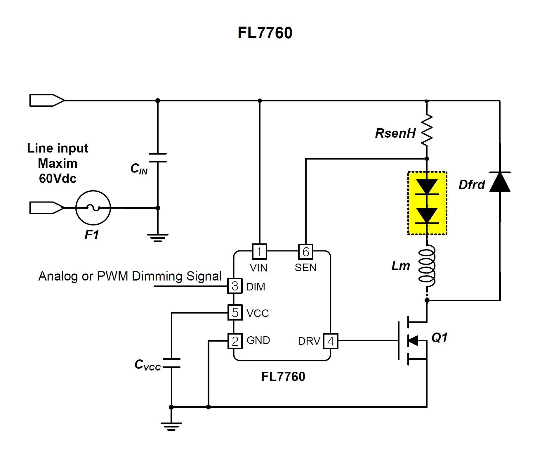
Figure 2. FL7760 application schematic. Image taken from the datasheet (PDF).
Dimming Options
As mentioned previously, this device allows for three input control methods for dimming its LED: PWM, analog (the control range being from 0.5V to 3.0V), and a hybrid scheme that combines analog and PWM (see image below).
Although all three input control signals use the same DIM pin (pin #3), ON Semiconductor suggests the following:
- Use version A (FL7760AM6X, as called out in their product overview and also listed on page 10 of the datasheet) for applications using analog dimming and having a wide-range dimming requirement.
- Use the ‘B’ version (FL7760BM6X) when PWM will be employed.
- For the hybrid method… well, they don’t offer a suggestion for this one. So, presumably either part would be acceptable, but if you plan on using the hybrid scheme you should probably contact ON Semiconductor to see if they have any advice.

Figure 3. Hybrid dimming. Image taken from the datasheet (PDF).
Wide Temperature Specification Ratings
If your LED lighting application requires a dimmer with extended/automotive temperature ratings, then you should definitely take a closer look at the FL7760. The spec for the maximum junction temperature (TJ(MAX)) is 150°C, and the storage temperature (TSTG) range is -65°C to 150°C.
However, what really caught my eye was the recommended operating ambient temperature range of -40°C to 125°C—keep in mind that this extended (AKA automotive) temperature rating is second only to the military rating, which is -55°C to 125°C. And if there’s concern that the IC may be subjected to extreme temperatures in your lighting application, the device has built-in thermal shutdown (TSD) protection circuitry to help ease your worries. According to the datasheet, “If the internal junction temperature is greater than 150°C, TSD protection is triggered and released with 30°C hysteresis.”
LED Dimming Range
With regard to the dimming range, the datasheet is very clear in specifying, for the analog dimming control option, that the LED can be dimmed down to 5%. However, for the PWM dimming range, the datasheet isn’t so clear. It states, “Wide PWM dimming duty range to 0.2% at 2 kHz PWM freq.” So what about when the PWM frequency is operating at speeds greater than 2 kHz, such as for the recommended maximum operating frequency, which is 1 MHz?
PCB Layout Guidance
The datasheet provides recommended physical locations/placements of bypass caps and the current sense resistor, as well as where to connect the two grounds—SG (signal ground) and PG (power ground). Layout details such as these are always appreciated.

Figure 4. PCB layout guidance. Image taken from the datasheet (PDF).
Have you had a chance to use this new LED constant-current dimmer? If so, leave a comment and tell us about your experiences.


Haven’t used this one, but it’s pretty typical of these small LED drivers, although surprised it needs an external FET. I was selling a complete driver board 10 years ago that used a Zetex ZXLD1360 and that was a similar device, although input voltage was limited to 30V, but it had an internal FET so driver PCBs would end up being pretty small. It can output up to 1A of current, has soft start, up to 95% efficiency, PWM or voltage dimming. The ZXLD1366 can handle up to 60V input and still has an internal FET, so there’s nothing special about the FL7760, just a rehash of existing designs, like many of these devices.