Facebook
 Google
 GitHub
 Linkedin
How Do You Design an LC Low-Pass Filter for a Class D Amp?
What's the role of low-pass filters in class D amplification? We'll use ST's new class D amp to discuss this question.
STMicroelectronics recently released the AEC-Q100-qualified FDA901, which can deliver up to 50 W per channel. In this article, we’ll discuss low-pass filters used in class D amplification.
Efficient Audio Amplification
Low power consumption is an increasingly important and widespread design goal for electrical engineers, and audio projects are no exception. Class D amplifiers are a means of incorporating high-efficiency design techniques into audio circuits.
As AAC contributor Lonne Mays points out in his article on choosing the right power transistor, on/off switching is now the most common method of controlling power delivery to a load, because this type of operation is inherently more efficient than linear regulation.
We introduce this type of operation into the domain of power-supply design by using switching regulators instead of linear regulators, and we can achieve a similar effect in the audio domain by using a class D amplifier instead of a linear topology such as class B or class AB.
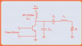
The following block diagram conveys the general architecture of a class D amplifier.

Block diagram of the architecture of a class D amplifier.
The analog audio signal is converted into a PWM digital signal by the comparator, and the digital signal is delivered to a power stage that performs the amplification. However, we definitely don’t want to send a digital signal to a speaker, and that’s why we need the low-pass filter: it suppresses the switching frequencies and recovers the sinusoidal nature of the original signal.

Class D amplifiers typically use a basic LC (inductor-capacitor) low-pass topology.
Low-Pass Filter Design for Class D Amplifiers
The low-pass filter in a class D amp is a crucial element of the overall design.
First, we must identify an appropriate cutoff frequency and choose component values accordingly. But this can be a bit tricky because the cutoff frequency depends not only on the filter components but also on the impedance of the speaker.
We also need to ensure that the filter’s response is not excessively overdamped or underdamped, but again, you need to be careful because the Q factor is influenced by the speaker impedance.
A third concern is distortion. Audio designers must always be especially mindful of distortion because of its undesirable effect on sound quality, and a class D amplifier’s output filter can introduce problematic quantities of distortion if the component values change too much in response to changes in the output signal.
We can choose components such that the inductance won’t vary significantly as output current changes and the capacitance won’t vary significantly as output voltage changes, but this may not be the preferred solution, because highly linear inductors and capacitors are more expensive and require more board space.
Low-Distortion Class D Amplification
The FDA901 accepts four channels of digitized audio via I2S, converts the digital data into analog waveforms, and produces four bridge-style speaker-drive signals by means of class D amplification.

FDA901 block diagram. Image used courtesy of STMicroelectronics
The device’s operation is controlled through an I2C interface, and it includes fault protection, clipping detection, and EMI-reduction features. Supported speaker impedances are 1 Ω, 2 Ω, and 4 Ω (check pages 8–9 of the datasheet for more information on speaker-drive configurations).
Filter in the Loop
As discussed above, designing the LC low-pass filter for a class D amp is not particularly straightforward. The FDA901 attempts to improve this aspect of class D implementation by means of a feedback topology that ST describes as “innovative.”
The basic idea here is that the LC filter is included inside the amplifier’s feedback loop, whereas in the more traditional class D architecture, feedback is taken from the output of the power stage rather than from the output of the LC filter.
ST indicates that this approach offers significant advantages and makes audio performance less sensitive to the characteristics of the filter. You can read more about this filter-in-the-loop approach on page 8 of the datasheet.
Have you found that class D amplifiers produce adequate audio quality in most applications, or is an all-analog solution (such as the class B Blomley amplifier) still preferable when the goal is extremely clean, rich sound? Feel free to share your thoughts in a comment.
Related Content