Facebook
 Google
 GitHub
 Linkedin
High Efficiencies, Small Package: An Integrated Boost (Step-Up) Module Regulator from Analog Devices
Linear Tech's new boost (step-up) module regulator comes in a small BGA package and offers high efficiencies.
Linear Tech's new boost (step-up) module regulator comes in a small BGA package and offers high efficiencies.
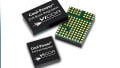
Linear Technology, now part of Analog Devices, has announced their new boost (step-up) µModule regulator, the LTM4661.
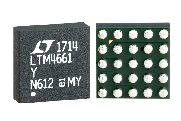
Image from the datasheet (PDF).
This power module operates from input voltages ranging from 1.8 V to 5.5 V, and is able to continue operation with an input voltage as low as 0.7 V after startup. Seems impressive!
This IC can generate output voltages ranging from 2.5 V to 15 V with continuous output currents up to 2 amps (see the figure below). According to the datasheet, in the section entitled Output Current Capability (page 8), the actual "output current capability depends highly on the input/output voltage ratio."
Also, be sure to pay close attention to the current-derating curves, when viewing the maximum output current values, and make use of the equations on page 8 when designing your circuit.
_specs.jpg)
As can be observed, the maximum continuous output current of 2 amps is only possible at a VOUT of less than or equal to 5 volts. Table from the datasheet (PDF).
Because of its integrated design nature, only a few bulk capacitors are required, at a minimum, for operation. For instance, when a VOUT of 1.2 volts is desired, no voltage-setting resistor is necessary (see the following figure). And when a VOUT other than 1.2 volts is required, only one resistor is needed.
The following figure, which includes a table for selecting the VFB resistor value, illustrates how easy and straightforward it can be to utilize this IC. For more information on setting the IC's output voltage, check out the section entitled Output Voltage Programming (page 8) in the datasheet.
_application_circuit_resistor_table.jpg)
Depending on design requirements, using the LTM4661 may only require external bulk capacitors. Image and table taken from the datasheet (PDF).
What is a "µModule Regulator"?
Now, if you're an active reader of these types of articles from All About Circuits, then the phrase "µModule Regulator" may look familiar. In fact, we referenced this phrase, as in the "µModule buck regulator," in a previous article that discussed Linear Tech's LTM8063. The LTM8063, which is a step-down (buck) regulator, should not be confused with the LTM4661—which, again, is a step-up (boost) regulator.
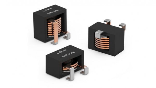
The term µModule, which is a registered trademark, serves seemingly as Analog Devices' catch-all label to describe their DC-to-DC fully-integrated system-in-package (SiP) power management solutions. So, when I say: "system-in-package (SiP) power management solutions," what I mean is that these modules contain the DC-to-DC controllers, the power switches, the compensation components, and the inductors, all within a compact BGA package.
Offers an Efficiency of up to 92%... Under Optimal Parameters
While this IC is said to offer efficiencies of up to 92%, which is indeed accurate, we must be mindful that these high-efficiency values are only attainable under specific parameters, such as VIN, VOUT, and IOUT (see the figure below).
_efficiency.jpg)
These graphs illustrate the fact that attaining high efficiencies is a function of the ICs parameters. Plots taken from the datasheet (PDF).
It's interesting to note that the Burst vs. Continuous Mode Efficiency plot omits the VOUT value. So, should it be assumed that these high-efficiency values are valid irrespective of VOUT? If you have insights into this assumption, please share them in the comments section.
Based on common input and output values, Linear Tech has provided the following table for quickly identifying efficiency capabilities as a function of VIN and VOUT. For more information on current capacity, head over to the section entitled Output Current Capability on page 8 of the datasheet.
_efficiency_table.jpg)
This table, from the datasheet, can be treated as a quick reference guide for determining efficiency levels as a function of common VIN and VOUT values.
Need More Current? Try Paralleling Multiple ICs
If your design requires more current than what's available from a single LTM4661 module, then consider adding additional parallel ICs. The following figure is an example of how two LTM4661 power modules are used in parallel.
_parallel_ICs.jpg)
An example of using two LTM4661 ICs in parallel. Taken from the Applications Information section on page 17 of the datasheet (PDF).
And, when it comes to selecting the voltage-setting resistor of paralleled ICs, simply use the provided equation (see figure below) on page 8 of the datasheet.
_parallel_IC_equation.jpg)
Linear Tech provides this simple equation for determining the voltage-setting resistor based on the number of paralleled ICs. Equation taken from the datasheet (PDF).
Evaluation Board
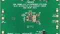
If you're interested in testing/playing with this new step-up/boost power module, there's a dev board available for the LTM4661, the DC2569A. Linear Tech/Analog Devices provides the demo board's design files and schematics and a demo board manual.
_eval_board.jpg)
The DC2569A is a demonstration circuit (i.e., demo board) for the LTM4661 voltage boost IC. Image courtesy of Analog.com.
Have you had a chance to use this new voltage boost µModule regulator from Linear Tech/Analog Devices, or its demo board? If so, leave a comment and tell us about your experiences.