 Facebook
 Google
 GitHub
 Linkedin
Teardown Tuesday: Immersion Cooker
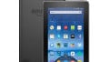
In this teardown, we open up an Immersion Cooker, from My Sous Vide.
In this teardown, we open up an immersion cooker, a device used in sous vide cooking.
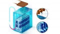
This 120VAC-powered immersion cooker from My Sous Vide is designed to help us cook better meals in our own kitchens. The company's slogan is: "If you can heat water, you can cook like a pro." (The notion of cooking better seems to be an ongoing quest for me.)
Sous vide is a cooking method wherein food is packaged and then submerged in hot water to cook, rather than baking or boiling. This is typically achieved with an immersion cooker, which is designed to heat water, monitor temperature, and circulate the water in a pot so that heat is distributed evenly.
Let's see what interesting things we can find inside this kitchen helper.

The immersion cooker is nicely packaged and comes with some helpful documentation.

The immersion cooker looks and feels to be a well-designed and well-assembled unit.
Let the Disassembly Begin
The two bottom pieces can be easily removed (see the figure below) simply by twisting to unlock and then sliding off. These pieces are designed to come off with little effort, for maintenance purposes, according to the documentation.

Removing the two bottom pieces was the easy part of this teardown.
With the two protective covers removed, all that remained for gaining access to the unit's innards was the removal of six screws...and some unexpected prying using two flathead screw drivers. The image below reveals wires, multiple PCBs, a rather hefty-looking motor, and an AC-to-DC power converter.

We begin to see a mixture of internal components
After disconnecting various cables, desoldering wires from PCBs, and with some "gentle encouragement," I was able to remove all the internal components. While the following figure shows some high-level identifications, the next section includes a closer examination of the PCBs and their components.

Major internal components
Inspecting the Numerous PCBs
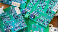
We'll now take a closer look at the assorted PCBs; there are five of them.

The five PCBs that may help us cook better meals.
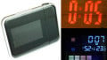
Display PCBs
The display panel makes use of two PCBs: one for activating the discrete LEDs and one for controlling the LED display panel and audio signal (i.e., buzzer).

Top-side and bottom-side of the two display PCBs.
The two PCBs that are dedicated to controlling the discrete LEDs and the LED display module are both 2-layer designs, meaning they have no internal layers. Minimizing PCB layers typically equates to cost savings. I say "typically" because if a, say, single 4-layer PCB can do the job of two 2-layer PCBs, then using a single PCB may be more cost-effective.
While these two PCBs both look to be well laid out, there's nothing overly fantastic about them.
- LED Display Module: Part marking CLC-4530BW 170665. No datasheet could be located.
- Microcontroller: Part marking STM8S005
- LED Controller: No part marking
- PNP Transistors: Part marking 2TY
- Shift Register: Part marking: NXP 74HC164D
Temperature Thumb Wheel PCB
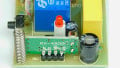
As can be seen in the figure below, the PCB that is responsible for housing the temperature-controlling mechanism is very basic in design. The temperature is set by use of a rotary encoder and a giant, relatively speaking, thumb wheel. Take notice of the rather large cutout in the PCB; it's worth mentioning that not all PCB manufacturers (i.e., board houses) offer this capability. One board house, that I've used multiple times, states specifically: "No internal routing/slots [allowed]."

The temperature-setting PCB is a very basic design: an encoder, two resistors, two LEDs, and a connector.
AC-to-DC Power Converter PCB
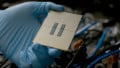
While the motor and the heating element both use 120 VAC, all the other electronics in this cooker use a DC voltage. The following figure calls out the major electrical components found on this AC-to-DC power converter board.

The immersion cooker's onboard power conversion occurs on this PCB.
- Transformer: Part marking EE-1315
- Safety Capacitor: Part marking CY/HTCC 102M
- Diode: Part marking SB34OL
- Voltage Management: Part marking OB2512NJP. Similar to this part
- Bridge Rectifier: Part marking MB10F
- Air Gap (slot): Used to maintain creepage requirements. Here's a good article on this topic
PCB for Motor and Heater Control
The PCB design utilizes triacs for controlling the power to the heater and the motor. Notice that the smaller triac—the one used for controlling the motor—does not require a heat sink, whereas the large triac (for the heating element) uses a fairly large heat sink.

A single PCB is used for controlling the motor and the heater.
- Triac Drivers (qty 2): Part marking MOC3041
- Triac (for the motor): Part marking: 131-6
- Triac (for the heater): Part marking: BTA16-600B
- Air Gaps (slots): Again, to maintain creepage requirements
- Fuse: 250V 10A. Similar to this one
The AC Motor
This motor, which is used to circulate the water, is a 120 VAC device (see the image below). It looks to be a solid unit and one that appears to offer a long lifespan. The white RTV—and lots of it—is used to keep water out of the electronics.

The 120 VAC motor...with some white goo (RTV).
Conclusion
This immersion cooker from My Sous Vide has a lot going on inside it with regards to electronics and controls. We can see the various systems for all three of the device's main functions: heating, temperature sensing, and water circulation.
Do you have any experience using this particular cooker? If so, leave a comment and let me know what you think of it, especially if you've had any problems with it. To me, it looks to be a fairly well-designed and well-built unit, but looks can be deceiving and I'd really like to know if it performs as well as it looks like it should.
Next Teardown: Bluetooth Padlock


Just like How the chinese like to tear down and copy all the US products…very interesting..keep up the good work.