 Facebook
 Google
 GitHub
 Linkedin
Learn About ATmega328P Fuse Bits and How to Use Them with an External Crystal Oscillator
This project introduces ATmega328P fuse bits and shows how to set them to use an external 16 MHz crystal oscillator.
This project introduces ATmega328P fuse bits and shows how to set them to use an external 16 MHz crystal oscillator.
Article Overview
Fuse bits, also known as fuses or configuration bits, are settings made in microcontrollers to control certain operations that are not normally changed during the execution of the program code. This article will explain what these operations are in the ATmega328P, and how to set them in general. The fuse bits for selecting the clock source will be dealt with in more depth, including the how and why of a 16 MHz external crystal oscillator.
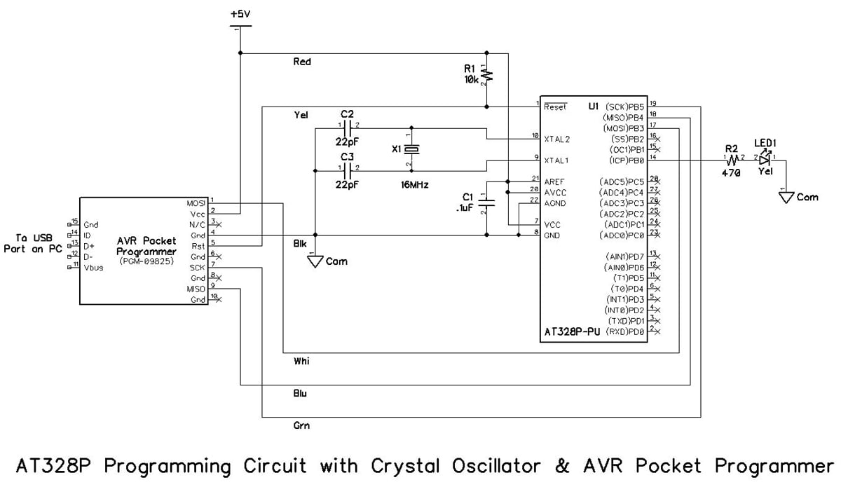
ATmega328P Programming Circuit
A simple programming circuit for the ATmega328P is shown in the photograph below. A schematic diagram, a complete parts list, and construction details are contained in a previous article. You will need the ATmega328P programming circuit as shown below in order to continue with this project.

ATmega328P Fuse Bits
Three Fuse Bytes
There are a total of 19 fuse bits that are used in the ATmega328P, and they are separated into three different fuse bytes. Three of the fuse bits are contained in the "Extended Fuse Byte", eight are contained in the "Fuse High Byte," and eight more are contained in the "Fuse Low Byte".
Table 31-5 from the November 2016 version of the ATmega328/P datasheet is reproduced below. As you can see, the entire Extended Fuse Byte deals with the Brownout detection level. Brownout detection is a feature of many microcontrollers that allows them to reset when the supply voltage falls below a certain level. In the case of the ATmega328P, one of three different voltages (nominally 1.8V, 2.7V, or 4.3V) may be selected as the minimum allowable supply voltage.
Perhaps the most important thing to notice from the table is that programming a fuse bit consists of setting it low, i.e., 0 (zero), which is the opposite of what you might have expected. For example, notice that each bit is unprogrammed when it is set to a logic high, i.e., 1 (one). This somewhat unusual method applies to all bits in all fuse bytes in the ATmega328P.
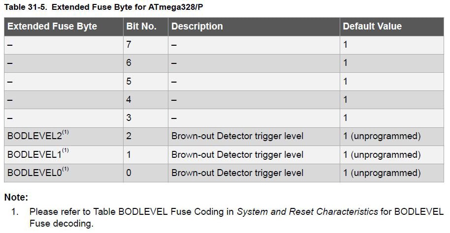
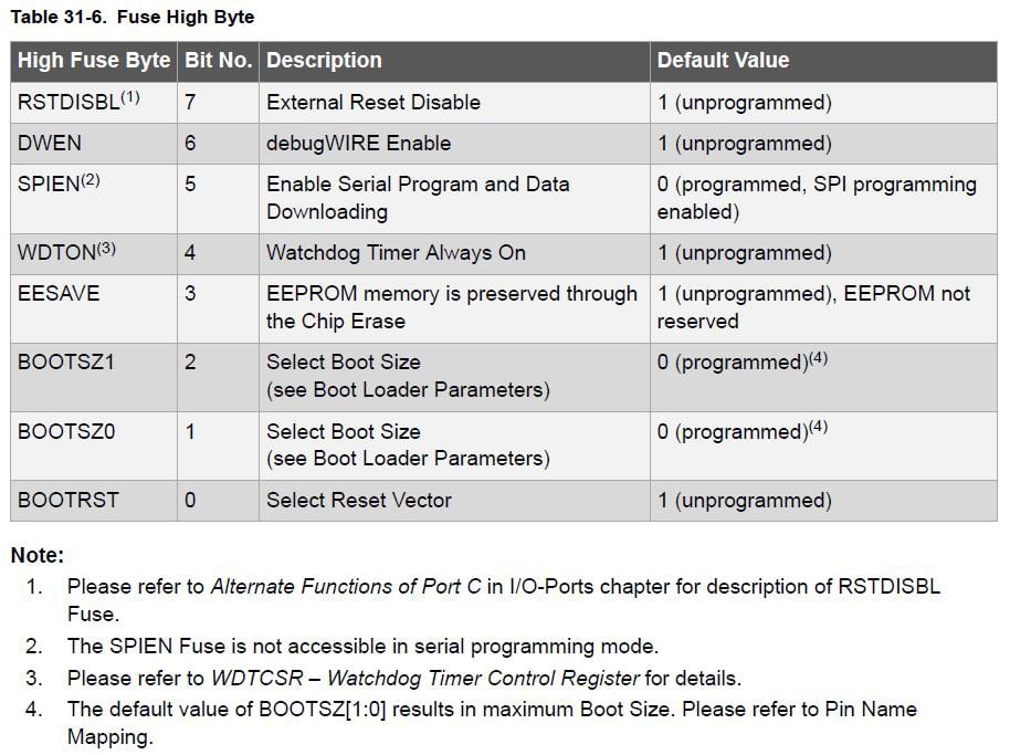
Table 31-6 from the datasheet is reproduced below. Bits 2-0 are used to set the boot size for the ATmega328P; boot size refers to the amount of memory reserved for the installation of a "Boot Loader" similar in function to the bootloader used in the Arduino line of development boards. The purposes of the remaining bits in the Fuse High Byte are made reasonably clear by the table entries. The two bits to be avoided unless you are absolutely certain you know what you are doing are bit7, the RSTDISBL (external reset disable) bit and bit 5, the SPIEN (Serial Peripheral Interface Enable) bit. Disabling either one is often the cause for "bricked" Atmel µCs; "leave them alone" is good advice.
Details of the purposes and setting procedures for all 19 of the fuse bits are contained in the ATmega328/P Datasheet; setting the Fuse Low Byte will be included in this article. However, the general process for programming all fuse bits is similar.
Fuse Low Byte Options
This Fuse Low Byte selects the clock source for the ATmega328P, and controls some of the details of the clock operation. Table 31-7 from the datasheet is reproduced below.
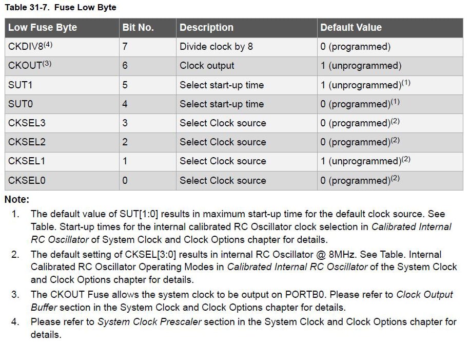
Don't forget that programming a fuse bit consists of setting it low, i.e., 0 (zero). For example, notice that bit 7 is used to enable/disable dividing the clock by 8; to enable division of the clock rate by 8, bit 7 is to be set to 0 (low), and to disable division of the clock rate by 8, bit 7 is to be set to 1 (high).
- Bit 7 controls whether or not the clock rate divide-by-8 feature is enabled, and bit 6 determines whether or not a clock output is present on PORTB0 of the microcontroller.
- Bits 5 and 4 control the start-up time of the microcontroller, which is intended to prevent the chip from attempting to start before the supply voltage has had time to reach an acceptable minimum level.
- Bits 3 through 0 are used to select the clock source, and table 13-1 presents the clock source choices that are available.

Fuse Low Byte Defaults
Wow! Admittedly, that's a lot of data to consider in order to set the 8 bits of the Fuse Low Byte, but it's all necessary and there's no "wiggle room." (At the risk of seeming overly critical, this author thinks that the datasheet could be written a bit more clearly to convey the details of this rather convoluted process.)
Fortunately, there's a lot of information that is made very clear in the datasheet; the default values that are programmed into the ATmega328P when it's shipped from the factory are unmistakable. Look back at Table 31-7, previously presented.
- Divide clock by 8 is enabled by bit 7 being set to 0.
- Clock output to PORTB0 is disabled by bit 6 being set to 1.
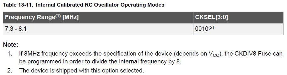
- Select clock source is set to the internal calibrated RC oscillator by bits 3, 2, 1, and 0 being set to 0010. (See Table 13-1 previously presented, and Table 13-11 show below.)
- Start-Up Time is partially dependent upon the oscillator type chosen and is set by bits 5 and 4. In the case of the internal calibrated RC oscillator, that information comes from Table 13-12. The programming of bits 5 and 4 (the SUT1 and SUT0 fuses) is specified for each of three power conditions. The default is for slowly rising power and results in a start-up time of 6 clock cycles after power-down or power-save, plus an additional 14 clock cycles and 65 milliseconds start-up time after a reset. See Table 31- 12 shown below.

You should now have an understanding that the Fuse Low Byte is pre-programmed to 01100010 (which, in hexadecimal notation, is 0x62), and what that means for the operation of the microcontroller. If any part of that isn't clear, don't be surprised; it's a complicated subject. Your time would probably be well spent re-reading the applicable parts of Sections 13 and 31 of the ATmega328P datasheet.
Now, Make Some Changes
If you are familiar with the Arduino family of microcontroller platforms, especially the Arduino UNO, you probably recall that it uses an ATmega328P µC. Perhaps you also remember that the UNO has an external oscillator circuit consisting of a 16MHz crystal and two small ceramic capacitors (often about 22pF each). You may also recall that the operating speed of the UNO is 16MHz.
But what about the ATmega328P? Can you determine its default operating speed when it's shipped from the factory?
You know that the ATmega328P default clock is an internal RC oscillator, but do you recall its speed? The answer is in Note 2 of Table 31-7: 8MHz. And because the default value of bit 7 of the Fuse Low Byte is 0, division of the clock rate by 8 is enabled. Thus, the default operating speed of the ATmega328P is...wait for it...1 MHz.
But suppose that your project called for a clock speed for the ATmega328P of 16MHz; would you know how to accomplish that? As usual, there's both hardware and software involved.
Hardware: Add a Crystal Oscillator
In order to run an ATmega328P at 16MHz, you would need to add an external crystal oscillator to the circuit shown at the very beginning of this article. Only three new parts are required: a 16MHz crystal (Jameco #325139) and two 22pF ceramic capacitors (Jameco #81533). The resulting schematic diagram is reproduced immediately below, and a photo of the breadboarded circuit is just below the schematic.

Software: Change the Fuse Low Byte Settings
Once you have added the 16MHz crystal oscillator circuit and double-checked your wiring, the next objective is to determine what changes to the fuse bits are required for a low power crystal oscillator. The Extended Fuse Byte and the Fuse High Byte are unaffected by an oscillator change; only the Fuse Low Byte needs to be changed.
Warning! Don't change the clock source to an external crystal unless you actually have the crystal installed. If you do, there will be no clock for the ATmega328P, and therefore no way to reprogram it.
Consider the Fuse Low Byte bit-by-bit.
- Bit 7 controls the divide-by-8 operation and the default setting of 0 has the feature enabled, which you don't want. So, bit 7 needs to be changed from 0 to 1.
- Bit 6 controls the clock output to PORTB0, which you don't care about. So, bit 6 can be left set to 1.
- Bits 3-0 control the oscillator choice, and the default setting of 0010 is to use the calibrated internal RC oscillator, which you don't want. You want the low power crystal oscillator, and according to table 13-1, bits 3-0 should be set to 1111, 1110, 1101, 1100, 1011, 1010, 1001, or 1000, but which one? Read on.
Table 13-3 indicates that for operation from 8.0 to 16.0 MHz, bits 3-1 (CKSEL[3:1]) should be set to 111. But what about CKSEL[0]? Read on.

Bits 5 and 4 control the startup time, and the default setting of 10 is for a startup delay of six clock cycles from power-down and power-save, plus an additional startup delay of 14 clock cycles plus 65 milliseconds from reset. From table 13-4, to be on the safe side for a low power crystal oscillator, you want the maximum delay possible of 16,000 clock cycles from power-down and power-save, so SUT[1] should be set to 1, plus an additional startup delay of 14 clock cycles plus 65 milliseconds from reset, so SUT[0] should be set to 1. In addition, CKSEL[0] should be set to 1.

Thus, bit 7 is 1, bit 6 is 1, bit 5 is 1, bit 4 is 1, bits 3-0 are 1111. Therefore, the new Fuse Low Byte should be 11111111 which, in hexadecimal notation, is 0xFF. Whew! You finally got there!
Avrdude
Avrdude is a command-line driven utility that is explained in more depth in this article. It is the only software tool required to program changes to the fuse bytes in the ATmega328P and a long list of other Atmel microcontrollers. The screen snip below is from an actual session of avrdude being used with an AVR Pocket Programmer connected to an ATmega328P as shown in the schematic diagram and solderless breadboard assembly earlier in this article. Line numbers have been added to the screen snip to make it easier to reference specific parts of the programming session.
Lines 1-3 were generated by avrdude as soon as the program was started.
Line 5 shows the active directory being changed to the location where avrdude was installed. In this case, the directory created and used was also called "avrdude." You should change to the directory where you installed avrdude on your computer.
Line 7 is a command to tell avrdude what programmer is being used and what Atmel microcontroller is attached. In this case, the AVR Pocket Programmer uses the USBTiny driver, and the microcontroller being used is an ATmega328P.
Lines 9-17 are the responses from avrdude. Line 13 presents the ATmega328P signature in hexadecimal notation: 0x1e950f. Line 15 presents the fuse bit programming currently in the ATmega328P also in hexadecimal notation; in this case, fuse bytes are programmed per factory default. The Extended Fuse Byte is 0xFF, the Fuse High Byte is 0xD9, and the Fuse Low Byte is 0x62.
Line 20 is a command to tell avrdude what programmer is being used and what Atmel microcontroller is attached and to change the Fuse Low Byte to 0xFF.
Lines 22-45 are the responses from avrdude. Each line presents the step that was done, and line 43 presents the new fuse bit programming in the ATmega328P. The Extended Fuse Byte is 0xFF, the Fuse High Byte is 0xD9, and the Fuse Low Byte is 0xFF.
Line 48 is a command to tell avrdude what programmer is being used and what Atmel microcontroller is attached and to change the Fuse Low Byte to 0x62. (Setting the Fuse Low Byte to 0x62 is necessary only if you want to change back to the original configuration because 0x62 is the default value.)
Lines 50-73 are the responses from avrdude. Each line presents the step that was done, and line 43 presents the new fuse bit programming in the ATmega328P. The Extended Fuse Byte is 0xFF, the Fuse High Byte is 0xD9, and the Fuse Low Byte is 0x62. Now, the fuse bytes are once again programmed per factory default.

"Burning" the Fuse Low Byte
Once everything (hardware and software) is ready, actually reprogramming fuse bytes is rather anticlimactic; it happens so quickly that if you don't watch closely, you might miss it. So, providing some evidence of the changes that were made is worthwhile. It's easy enough to do that by using the same LED blinking software used in Breadboarding and Programming the ATmega328P & ATtiny45 in Atmel Studio 7. If it's still programmed in your ATmega328P, you're ahead of the game; if not, download it using the button below and install it.
New Blink.c flashes the yellow LED on for ½ second and off for ½ second, 60 times per minute. Check to be sure that it is still doing that in your breadboard assembly.
As you (hopefully) recall, the ATmega328P is using its calibrated internal oscillator and does not rely upon the 16MHz crystal oscillator you just added. At this point, the crystal is being ignored because of the fuse low byte setting. (Remember that the fuse low byte is still set to its factory default of 0x62, which specifies the use of the internal oscillator.) Fortunately, the presence of the crystal and its two 22pF capacitors does nothing to prevent the use of the internal oscillator. To make the change to the 16MHz crystal oscillator, perform the following two steps.
- First, start avrdude, then follow the procedure described in lines 4-17 of the screen snip above. The result should confirm that the fuse low byte is still set to 0x62, which specifies the use of the calibrated internal oscillator.
- Second, follow the procedure described in lines 20-45. The result should confirm that the fuse low byte is now changed to 0xFF, which specifies the use of the crystal oscillator.
Watch the yellow LED; do you notice that the flash rate has changed? Here's why.
Not only does a fuse low byte value of 0x62 call for the use of the internal 8MHz oscillator, it also specifies that the divide by 8 feature is enabled. Therefore, the effective rate of the oscillator is 1MHz, a fact which is reflected in line 3 of the New Blink.c code depicted below. (It is important to understand that line 3 doesn't control the speed at which the ATmega328P runs, but rather, it tells the compiler that the microcontroller is supposed to be running at 1MHz in order for the code to execute at the right speed.)

Because you have changed the fuse low byte from 0x62 to 0xFF, you have changed the oscillator being used to the 16MHz crystal. In addition, you have disabled the divide by 8 feature. The net effect of those two changes is that the ATmega328P clock is now running at 16MHz, but line 3 in New Blink.c is still telling the compiler that the microcontroller is running at 1MHz. Therefore, the flash rate is 16 times faster than it should be. What to do?
Start Atmel Studio 7, and change line 3, of course. Instead of #define F_CPU 1000000UL, make line 3 read #define F_CPU 16000000UL, which tells the compiler that the clock is now running at 16MHz. Then, rebuild the project, and download the revised code to the AT328P. Almost immediately, the LED will resume flashing on for ½ second and off for ½ second, 60 times per minute, which is exactly what you want.
An Easier Way?
"Isn't there an easier way?" you might ask, and the answer is "yes." There are some on-line applications that will determine the fuse byte settings to reflect the features chosen, and one of the most popular is EngBedded's AVR Fuse Calculator. However, web sites have a way of disappearing and it's always good to know how to do it yourself; that way you can understand the "how" and the "why" in addition to the "what."
What's Next?
The next article in this series will discuss the operation of Atmel Studio 7 in some more detail and will present a much less expensive way to have a genuine Atmel ICE programmer. It's coming soon here on AllAboutCircuits.com.
Give this project a try for yourself! Get the BOM.


There’s an article on the Arduino website…
https://www.arduino.cc/en/Tutorial/ArduinoToBreadboard
...that would appear to imply that you don’t need to go through all this in order to get your ATmega328P running correctly, standalone, at 16MHz with an external crystal/caps. Or have I missed something?
The article on the Arduino website to which you refer describes the installation of a bootloader onto the ATmega328P which effectively turns it into an Arduino, which is enabled by the bootloader to use an external crystal. My article does not involve installation of the Arduino bootloader, and thus the steps I describe are required in order to use an external crystal. Thanks for your question.