Facebook
 Google
 GitHub
 Linkedin
How to Build a Robot - Line Follower
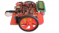
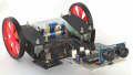
Part four of a series of articles on building a robot that can follow lines or walls and avoid obstacles!
Part four of a series of articles on building a robot that can follow lines or walls and avoid obstacles!
Related Articles
How to Build a Robot:
Part 1: Design and Schematic
Part 2: PCB Design
Part 3: Testing Hardware
Part 5: Avoiding Obstacles
Part 6: Wall-Following Robot
Overview
This is part 4 of a series of articles on my experiences building a robot that can do various things. I thought it would be neat to create a robot that was easy to put together with a single soldering iron and was also affordable. I made up the following requirements for my robot:
- Many kits are expensive, so it must be relatively inexpensive.
- It must be easily put together without special equipment.
- It must be easily programmable without a complicated IDE or programmer.
- It must be powerful enough for expandability.
- It should run off a simple power source.
- It should be able to follow a line or a wall, and avoid obstacles.
In this article I'll talk about how to program the robot to be a line follower.
Follow a line?
A line follower is the easiest way to make a robot follow a pre-determined path. You only need a way to move and a sensor to determine if the robot is on the line or not. There have been may algorithms developed to keep the robot on the line. The field of engineering that covers these algorithms is called control theory. For this article, I'm going to make a really simple algorithm. In pseudo code:
is robot to the left of the line?
    turn right
is the robot to the right of the line?
    turn left
is the robot on the line?
    move forward
Finding a suitable surface
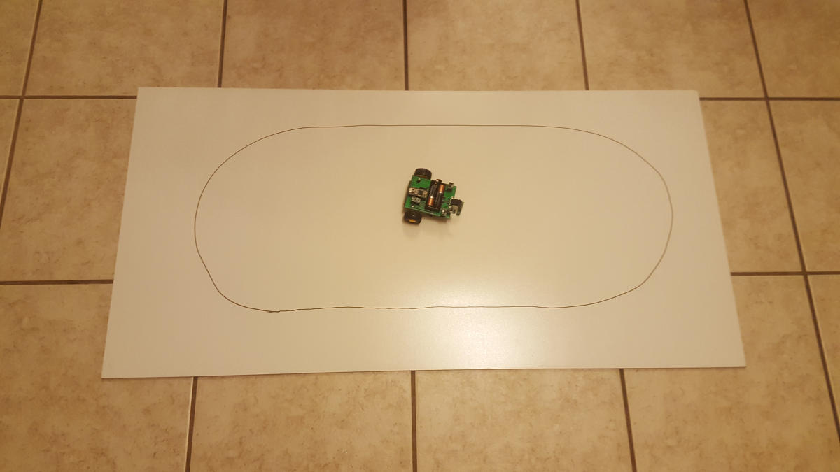
Many people use black electrical tape on the floor to do robots. This is a huge pain and creates a mess. A white dry erase board is a great surface to try out different line following courses. I found this 2x4' board at Home Depot for $10. You can easily add tracks by drawing with a black marker. The white background and the black marker have enough contrast so that the sensors can easily distinguish the line. Rather than calibrate the sensors for every surface, I'm going to assume that they all read approximately the same for a given color. Then I can compare them relative to one another to determine which sensor is currently reading the darkest value. As long as the line I draw only covers up one sensor at a time, this algorithm will provide a reliable way to determine the position of the robot.
Writing the Program
The code below begins by initializing the robot driver and then waiting 5 seconds. This allows me enough time to put the robot on the track before it starts moving. After that, the robot continuously checks the sensors and determines how to move using the algorithm above. The forward speed can be set using the ROBOT_SPEED define. This is a number out of 255. If the robot moves too fast, the algorithm may not have enough time to correct the motion. I also added a check for if the robot is picked up or is about to fall off the course. If all the sensors are reading 1000, that means the robot is most likely off the ground because none of the light is reflecting back. This is useful if you want the robot to stop while you're moving it around.
Potential Improvements
This algorithm does not use averaging or keep track of error. You'll notice in the video below that sometimes the robot looks like it's shaking back and forth. This is caused by oscillations in the algorithm because the robot overshoots the line. One method to fix this would be to use a PID (proportional-integral-derivative) algorithm. In a nut shell, this type of algorithm keeps track of where the robot was (integral), where it might be going (derivative), and where it currently is (proportional). The algorithm I implemented only cares about what is currently happening to the robot. If you wanted to have a faster robot, you would likely need to remove the oscillations (over-corrections) that are slowing the robot down.
#include "robot.h"
#define ROBOT_SPEED  100

void setup()
{
  Serial.begin(38400);
  Serial.println("Boot");
  rbt_init();
  delay(5000);
}

uint16_t lleft,lmid,lright;
boolean wleft,wmid,wright;
void loop()
{
  rbt_sns(&lleft,&lmid,&lright,&wleft,&wmid,&wright);
  Serial.print("Left: ");
  Serial.print(lleft);
  Serial.print("Mid: ");
  Serial.print(lmid);
  Serial.print("Right: ");
  Serial.println(lright);
  //off the line
  if(lleft == 1000 && lmid == 1000 && lright == 1000){
    rbt_move(BRAKE,0);
  }
  //follow track
  else{
    if(lleft > lmid && lleft > lright){
      rbt_move(LEFT,ROBOT_SPEED);
    }
    if(lmid > lleft && lmid > lright){
      rbt_move(FWD,ROBOT_SPEED);
    }
    if(lright > lmid && lright > lleft){
      rbt_move(RIGHT,ROBOT_SPEED);
    }
  }
}
Follow a line!
Conclusion
In this article I showed the process of writing a control algorithm to follow a line. A line follower is a neat way to learn about control theory and watch a robot navigate a course completely autonomously! In the next article, I'll make the robot navigate around a floor and avoid bumping into obstacles and walls.
Next Article in Series: Build Your Own Robot - Avoiding Obstacles