 Facebook
 Google
 GitHub
 Linkedin
Build Your Own LED Saber—Firmware, Microcontroller, and Testing
In part 3, we compile the firmware and build the controller at the heart of the Saber, then do initial testing and diagnostics.
In part 3, we compile the firmware and build the controller at the heart of the Saber, then do initial testing and diagnostics.
My goal in this series is to teach you how to build the brightest LED lightsaber to date. Please check out the first articles in the series before continuing:
In this article, we'll go over firmware and how to install the microcontroller. Then we'll do some bench testing.
The Saber Controller
The WS2812b LED is a digital device. Applying power to the Neopixel strip isn't enough—it will remain dark unless commanded by a serial connection. So we'll need a microcontroller. And once that's assumed, we may as well stuff it full of all the software features we can fit because software weighs nothing and is essentially free.
I’m very fond of SparkFun’s “Pro Micro”, which is a shrunk-down Arduino Leonardo. It also cold-boots faster rather than waiting around seconds for the IDE.
The MPU-6050 is a well-known triple-axis accelerometer and gyro that talks I2C. It's very common on breakout boards from many sources. If we want the saber to respond when it's moved, we need a sensor like this one.
The suggested rotary ‘digital volume’ encoder/switch can be extracted from boards that are common in Arduino kits. I get mine in bags for half a dollar each.

"The Crystal is the Heart of the Blade." In this case, it runs at 16MHz and has a companion sensor chip.

Prepare the Firmware
First, we need to upload our Arduino firmware to the "bare board" before we start the build. Hopefully you are familiar with Arduinos and have the IDE already set up. You will need the FastLED library installed. You may have it already. If you don't, use the link, click on "Clone or Download", and save as a .zip file.
In the Arduino IDE, select the menu "Sketch" >> "Include Library" >> "Add Zip Library..." and give it the file you just downloaded. This is the same procedure as used for installing any Github-hosted library.
FastLED is the de-facto standard for dealing with WS28xx LED arrays and has more features than I have space to describe.
Download the LEDSaber firmware:
Update: The firmware was updated on May the 4th, 2017. The latest version with bug fixes and new features can be found here.
Uncompress the .zip file and open the LEDSaber.ino sketch using the Arduino IDE.
At the top of the sketch are the most important parameters. If you're building everything as described, you don't need to change anything and are good to go.
The most common mod is likely to be the number of LEDs in your blade strip and the pin for the connection:
// define our LED blade properties
#define BLADE_LEDS_COUNT  72
#define BLADE_LEDS_PIN    A2
Remember we're driving 144 LEDs as a mirrored strip of 72. If you have fewer LEDs, you can leave BLADE_LEDS_COUNT as is, but using a higher-than-necessary value will chew up memory and processing time, so don't go overboard. If you have more than 72 LEDs, the data stream will stop short of the end of the blade.
// default colour customization
#define BLADE_SATURATION  255
#define BLADE_HUE         144
// see properties.h for the presets list
These set the startup blade color. I've chosen Jedi blue as the default. This color is defined by 'hue' (where it is on the rainbow) and 'saturation' (higher saturation means a more rich, pure color, and lower saturation means a more dull or pale color).
The FastLED's HSV Rainbow is here.
The "properties.h" file has a bigger array of colors/audio parameters for the eight presets. Once you have a little experience with the saber, you might like to customize these.
// voltage shutdown properties
#define VOLTAGE_SHUTDOWN       (3.5f * 3.0f)     // minimum voltage required
#define VOLTAGE_SENSOR_RATIO   (2.10f / 12.60f)  // ratio between sensor voltage and real battery voltage (1:6 by default)
#define VOLTAGE_SENSOR_PIN      A3               // pin used by voltage sensor
The undervoltage shutdown settings are the most important. If your voltage divider is not 6:1 or you're using a different battery, you will need to adjust VOLTAGE_SENSOR_RATIO and/or VOLTAGE_SHUTDOWN based on measurements of the battery and sensor voltage and on the characteristics of the battery.
It's a good idea to empirically fine-tune the VOLTAGE_SHUTDOWN threshold before assembly. You can do this by turning on the saber and leaving it on as you monitor the battery voltage using a multimeter. If the undervoltage shutdown kicks in too early, lower the threshold. If it kicks in too late (i.e., you hit 10.5 V without a shutdown), increase the threshold.
Notice that we are using an undervoltage threshold of 3.5V per LiPo cell. In some discharge situations, this number could be considered rather low. However, keep in mind that the battery voltage is being measured under load. Cell voltages will spring back 0.1V or more as soon as we halt our current draw.
Upload the Firmware
Make sure the Pro Micro isn't going to touch anything metal. Plug the Pro Micro into your computer's USB port. The usual beeps should sound.

In the Arduino IDE, use the menu "Tools" >> "Port" and select the device you just plugged in.
Use "Tools" >> "Board" and pick "Arduino Leonardo" to tell the IDE what kind of board it is.

Click the "Verify" tick button and make sure everything compiles. (I really wish library authors wouldn't #pragma. It's untidy.)
You should see the following output:

Click the "Upload" arrow. The code will be compiled again and should be sent to the device in a flurry of blinking lights.
And that's it.
Add the Rotary Switch
Next, we mount the rotary switch directly on the Pro Micro. It has three pins on one side for the rotary encoder and two pins on the other for the switch. By doing this, we avoid the need for five jumper wires, which in turn accomplishes three things: we eliminate ten points of likely failure, we make it possible to securely bolt the controller to the case, and we save space and weight and time. The switch is very compact for the functionality it provides.
The side with three pins goes in holes 16, 14, and 15. The two pins (with a gap between them) go in 6 and 8.

Some rotary switches have tabs that would interfere. Wiggle them with pliers until they fall off.

The switch should be up off the board, not shorting components with its metal base.
Note well: Leave the last holes EMPTY. Pin 10 is where the audio comes out.
If you need to trim down the shaft of the switch, do that before you attach it to the Pro Micro! Grip the end of the shaft in a vise and trim with a Dremel or hacksaw. Don't put the main body of the switch in the vise—the shaft will spin uselessly and the switch isn’t likely to survive the cutting forces.
When cutting metal, please do it far, far away from electronics and wash your hands and change your clothes before coming back. Seriously. One stray metal filing in the wrong place will ruin a project in the worst possible ways, sometimes months later.
Mount the switch on the component side of the Pro Micro by laying the Arduino on a flat, hard, heat-proof surface (you can use a piece of paper underneath the components for extra protection, if needed). Then set the switch's pins in the holes such that everything is nice and level. (Don’t crush/short the Pro Micro crystal or other parts!) Now you can solder from the upper side.
For those who don't want to bother with the switch, I'll point out that it is not a strictly essential part of the blade system. However, if you choose to leave it out, you will lose a great deal of functionality—all ability to change settings on the fly during use and the most basic way of igniting and extinguishing the LED blade. But this is not the only way to light the blade; the swing-to-ignite feature allows you to light it up and the inactivity shutdown (or main power switch) can turn it off.
Actually, you can have a hilt with no external controls at all, so long as you can unplug your battery safely and easily.
Adding the MPU-6050 IMU
The MPU-6050 comes on breakout boards in many shapes. We only care about the four pins for GND, VCC, SDA, and SCL.
Because the Arduino I2C data/clock lines are right next to each other on pins 2 and 3 (and they are also usually together on the IMU), I recommend directly mounting the IMU on the “back” of the Pro Micro using two standard 0.1-inch header pins, with the insulation conveniently functioning as a spacer.
.

If the SDA/SCL pins seem to be in the wrong order, just flip the IMU over.
If you’re very lucky, it’s possible the GND or VCC pins will also line up nicely. Mine didn’t, so I ran appropriate wires (before I soldered the pins) in the space between. This creates a very neat package.
My rotary encoder switch and IMU breakout board were too large to fit on the same side of the Pro Micro (by about a millimeter!) but you might have more options for placement. I wasn’t entirely happy with how exposed the IMU was, hanging off the back component-side up, so later I coated it with silicone goo for protection and put some into the gap to prevent flexing.

Two pins connect the I2C bus and physically mount the board. Power wires run in between.

Add Servo Connectors
We use a servo plug to get power from the power converter and a socket to supply the data connection to the blade.
The voltage sense from the converter goes to pin A3 on the Pro Micro and the wire going to the socket connects to pin A2. (These are changeable in the firmware if needed.)
In a sense, the control module acts like another “converter” block, taking volts and turning them into data. Or maybe a very complicated light-switch.


Voltage sense goes to A3, the closest analog input to the GND/RAW pins. Control data comes out next-door on A2 and goes to the LED strip.
Safely Reprogramming the Arduino
You may wish to modify the firmware after the saber is complete. Heed this warning.
NEVER connect the LiPo battery when the USB port is also connected; by doing this you are essentially shorting the outputs from two separate power supplies, and that's a bad idea unless you want 20 amps coming back down the USB cable into whatever is at the other end. Probably your favorite computer. Maybe your PC is well made and will survive that, but it's just as likely there will be smoke and sadness.
Remember: Don't allow two independent power supply rails to be shorted together. In this project, that means don't short the DC/DC converter's 5V to the USB's 5V. Never cross the streams!
… actually, the Pro Micro (the current genuine version) has a protection diode and polyfuse that should make that completely safe. Otherwise, I’d have designed it differently. (Never build in a self-destruct mechanism!) But there are variants and knockoffs out there that could easily omit those parts—and in any event, do you really want to gamble your computer’s life on someone else's supposed protection circuitry? It's best to avoid that whole situation.
I know it’s tempting to leave it all plugged in for easy debugging, but don’t. Just don’t. Try to construct your hilt so you have to physically unplug/remove the ridiculously powerful battery to get to the USB socket.
If you’re planning on doing a lot of software development (as I did), I recommend constructing a "knife blade" with less than 40 LEDs for testing. At 2 amps max, that will just barely work off a "charging" USB port and you can write all the bad code you want. Note that there is NO WAY your computer can supply enough current to run the full 1-meter strip, and the polyfuse on the Pro Micro should trip and interrupt the current if you try.

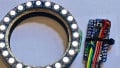
The 40-LED "Light Knife" I used for development can be sufficiently powered by a high-current "charging" USB port.
Connect the Audio Module


Completed audio module from Part 2.
We need a good amount of 5V power for the audio amp (as much as 2W!) so connect its power wires to GND and RAW on the Pro Micro. You can do this by shoving the wires from the power harness and the wires from the audio module into the GND and RAW holes (then solder as usual). Put a dab of hot glue or silicone over these connections for strain relief and protection. Be careful here; this is the closest those 20 amp rails come to touching.
Don’t connect the audio power to the Pro Micro's VCC pin—that would steal from the regulated “digital” power supply. VCC should power only the Pro Micro and the MPU-6050.
I chose to wire the audio/speaker module directly to the Pro Micro because I was running out of space, but feel free to add another servo connector here if you like (or mini-JST connectors if you have them).

Audio module wired to the controller.
Initial Bench Tests
Once the control and audio modules are assembled, plug them into a small USB power supply/bank (not the main power converter or your computer in case something goes wrong) and you should hear a horrible beeping noise. This is the undervoltage alarm; in this case it's simply reminding you that there's no LiPo plugged in.
If that works, you can do an initial test with the power converter and battery. Unplug from USB, connect the four modules we have completed in the proper chain (controller, power converter, harness, and battery), watch out for shorts, and do your first 'ignition' test.
Turn the power switch on. There should be a 'click' from the speaker but no undervoltage alarm like with the USB. If the alarm sounds (even though there's definitely a full battery) you may need adjust your firmware settings.
Turn the control knob clockwise to ignite the blade or "bump" the controller (I usually lift one corner and drop it again) to give it enough rotation to activate the 'swing to ignite'.
There should be a sudden, loud, semi-unpleasant tearing noise from the speaker that settles into the familiar hum. You can (gently) move the controller module around to hear the hum change subtly. That will prove the IMU is working.
If the saber constantly shuts down after about 90 seconds and the sound doesn't respond to movement, it's likely the IMU isn't communicating with the Arduino. Check that it has power and the I2C lines are the right way around.
For audio testing, rest the speaker face-down inside a PVC end-cap (or on the end of a cut-off segment of tube) so you know what it’s going to sound like when inside the hilt. Speakers work best when there is a ‘baffle’ between the front and back faces; otherwise, the sound pressure waves just nip around the edge of the speaker cone and cancel out.
Adjust the volume control on the speaker module so the hum and ignition sounds are at their best—loud but not distorted.

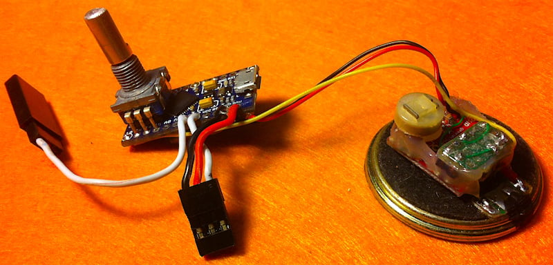
Five out of six modules connected and ready for bench test. Igor, throw ze switch!
If you do have persistent crackly static, a high-pitched whine, or other audio issues at this stage (basically, if you can hear anything coming from the speaker while the blade isn’t active), you may need to add a 330μF or 470μF electrolytic capacitor across the audio amp's power supply. This may be the case especially if you picked an SBEC other than the YEP-20.
WS2812b LEDs internally use pulse-width modulation and a hundred together can make a choral “singing” sound that gets into the audio signal via the power supply lines. If you suddenly hear that kind of noise once we add the blade, you’ll definitely need extra smoothing capacitors.
Next Time...
Are you disappointed your favorite microcontroller / IMU or combination wasn't used? Suggest which other platforms you'd like to see the firmware ported to in future in the comments below.
Related Content


I was wanting to ask few questions about his project.
first, how would the code need to be changed for a RGB LED star instead of
the string blade.
would the shutdown voltage be neccessary if im using a lithium ion PCB
protected battery (7.4v Li-ion 1400mAh 18500 Battery Pack)
how would you modify the code to include adafruits BLE module that allows
color mixing via a phone app
and would the code need to be very different for adafruit pro trinket 5v
module?
i am a complete noob with arduinos and currently the language is completely
foreign to me.
it would really be nice to find a line by line explanation of this code so i
could begin to understand what its all doing and its purpose.
i appreciate any info i can get.