 Facebook
 Google
 GitHub
 Linkedin
Understanding and Implementing the HC-12 Wireless Transceiver Module
The HC-12 is a 100mW multi-channel wireless transceiver you can use in your projects to transmit and receive serial information.
Learn about the HC-12 transceiver module and how to use it to transmit and receive digital data.
The HC-12 is a half-duplex wireless serial communication module with 100 channels in the 433.4-473.0 MHz range that is capable of transmitting up to 1 km. This project will begin by using the HC-12 to create a wireless link between two computers and end with a second article that creates a simple wireless GPS tracker.
Parts Required
| Item | Cost | More Information |
|---|---|---|
| HC-12 transceiver (x2) | $4 | Datasheet |
| IPEX-to-SMA adapter (optional) | $3 | Specification |
| Arduino Uno R3 (or compatible) | $10 | Reference |
| GPS Receiver (x2) | $16 | Datasheet |
| or Adafruit GPS Logger Shield (x2) | $45 | Project Guide |
| 433MHz antenna | $2-$5 | Datasheet Search |
About the HC-12
The HC-12 is a half-duplex 20 dBm (100 mW) transmitter paired with a receiver that has -117 dBm (2×10-15 W) sensitivity at 5000 bps.
Paired with an external antenna, these transceivers are capable of communicating up to and possibly slightly beyond 1 km in the open and are more than adequate for providing coverage throughout a typical house.
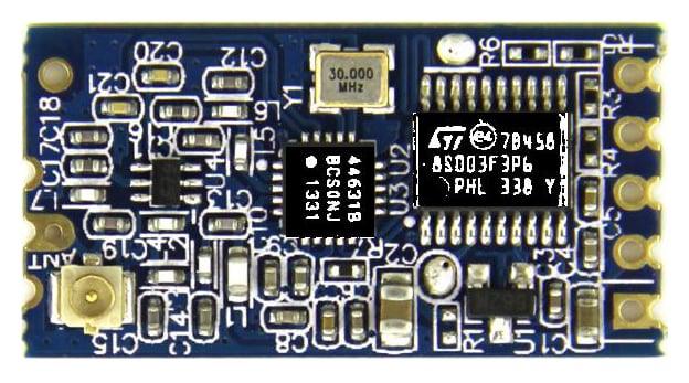
The HC-12 circuit board. Image courtesy of Seeed. This image has been digitally manipulated to enhance chip markings.
The HC-12 circuit board is built around the STM8S003F3 microcontroller and the Si4463 transceiver.
The Si4463 Transceiver
The Si4463 provides the wireless communication in this circuit. It has a maximum transmit power of 20 dBm (100 mW) and receive sensitivity of -129 dBm. Two 64-byte Rx and Tx FIFO memories are built into the chip along with a great many advanced features that are not implemented in the HC-12 design. See the datasheet for more information on multiband operation, frequency hopping, etc.
The STM8S003FS Microcontroller
This is an 8-bit microcontroller with 8 kB of flash memory, 128 bytes of EEPROM, and a 10-bit ADC. It supports UART, SPI, and I²C and has multiple I/O pins. It offers many of the same capabilities as its ATMega and XMC counterparts. It is programmed to control the Si4463 as well as handle the UART communication between the HC-12 and whatever it is connected to on the other end.
The HC-12 Transceiver Module
Combined with other components, the Si4463 and STM8S003 create the HC-12 transceiver, which provides a 4-pin TTL-level UART interface (Vcc, Gnd, Tx, Rx), with a 5th pin that is used to enter "command" mode for changing the module's configuration. The HC-12 has 100 supported channels spaced 400 kHz apart, eight transmit levels, eight supported baud rates, and three different working modes.

The 5th pin on the HC-12 is labeled "Set" and, when driven to logic low, allows various settings to be selected on the HC-12 using AT commands sent to the "RXD" pin.
The default configuration of the HC-12 is FU3—on Channel 1, FU3 is a fully automatic and transparent (to other devices) setting that adapts to the transmission rate of the connected device (although 9600 baud is still required to program it in Command mode).
Note that as the transmission rate increases, the sensitivity of the receiver decreases. You can return to the default state by sending AT+DEFAULT once in command mode.
| Serial Port Baud Rate | Over-the-Air Baud Rate | Receiver Sensitivity |
|---|---|---|
| 1200 bps | 5000 bps | -117 dBm |
| 2400 bps | 5000 bps | -117 dBm |
| 4800 bps | 15000 bps | -112 dBm |
| 9600 bps | 15000 bps | -112 dBm |
| 19200 bps | 58000 bps | -107 dBm |
| 38400 bps | 58000 bps | -107 dBm |
| 57600 bps | 236000 bps | -100 dBm |
| 115200 bps | 236000 bps | -100 dBm |
In "HC12 Send/Recieve Example Program 1," the HC-12s are used in their default state (FU3: 20mW transmit, 9600 bps, Channel 001) to create a wireless bridge between the serial ports of two computers. The transceivers must be physically separated by at least 1.5 meters to function.
This program will allow messages to be sent between two computers via the HC-12 transmitters. Text typed on one computer will be displayed on the serial monitor of the second computer.
Begin by connecting the HC-12 transceivers to each Arduino:
- Connect the HC-12 "Set" pin to Arduino pin 6
- Connect the HC-12 "RXD" pin to Arduino pin 4
- Connect the HC-12 "TXD" pin to Arduino pin 5
- Per the datasheet, connect a 22 µF to 1 mF reservoir capacitor in parallel with the HC-12 "Gnd" and "Vcc" pins
- Connect HC-12 "Gnd" and "Vcc" to a 3.2 V to 5.5V 200mA source. Per the datasheet, if powering the HC-12 with more than 4.5V, place a 1N4007 diode in series with the HC-12 "Vcc" pin

Upload the following code and open the serial port monitor in the Arduino IDE to send/receive messages.
The functions "*.available()" reads the number of bytes stored in the Arduino's Serial or SoftwareSerial FIFO buffers. As long as there is a non-zero value returned by "*.available()", the "*.read()" function pulls one byte out of the buffer and the "*.write()" function sends that byte along to the other serial port to be read by either the computer or the HC-12.
The Arduino UART has a 64-byte receive buffer built into the hardware so any bytes of data that exceed the 64-byte limit will be discarded. The software serial also has a 64-byte buffer; however, the SoftwareSerial library can be modified to increase that, if required.
/*  HC12 Send/Receive Example Program 1
    By Mark J. Hughes
    for AllAboutCircuits.com

    Connect HC12 "RXD" pin to Arduino Digital Pin 4
    Connect HC12 "TXD" pin to Arduino Digital Pin 5
    Connect HC12 "Set" pin to Arduino Digital Pin 6

    Do not power over USB.  Per datasheet,
    power HC12 with a supply of at least 100 mA with
    a 22 uF - 1000 uF reservoir capacitor.
    Upload code to two Arduinos connected to two computers.

    Transceivers must be at least several meters apart to work.

 */

#include

const byte HC12RxdPin = 4;                  // Recieve Pin on HC12
const byte HC12TxdPin = 5;                  // Transmit Pin on HC12

SoftwareSerial HC12(HC12TxdPin,HC12RxdPin); // Create Software Serial Port

void setup() {
  Serial.begin(9600);                       // Open serial port to computer
  HC12.begin(9600);                         // Open serial port to HC12
}

void loop() {
  if(HC12.available()){                     // If Arduino's HC12 rx buffer has data
    Serial.write(HC12.read());              // Send the data to the computer
    }
  if(Serial.available()){                   // If Arduino's computer rx buffer has data
    HC12.write(Serial.read());              // Send that data to serial
  }
}
"HC12 Send/Recieve Example Program 2" remains backward-compatible with "HC12 Send/Recieve Example Program 1." However, two significant changes have been made in the way data is handled by the Arduino.
In the first program, single bytes were detected and read from the serial buffer and software serial buffer and immediately written to the other serial port. The following program will read entire strings of data from the serial buffers and store it until a newline character is detected at which point it will write out the entire buffer.
The first program had no way to enter command mode and change the settings of the HC-12 transceiver. The following program can detect command sequences and change the settings of remote and local transceivers (provided they are running the newer version of the code). Note that it is important to change the settings of the remote transceiver first and then change the settings of the local transceiver to match, as any initial changes to the local transceiver will interrupt communication between the two.
The Arduino will collect strings from the serial port and software serial port. Once the new line has been detected, there is a check to confirm if the string is a command sequence (commands begin with AT+). If a command sequence is present, the local chip executes the command and transmits the command to the remote chip for execution there. The code keeps the HC12s on the same channel at same power levels during testing.
Use caution as it is possible to accidentally lower the remote power level to a point that the remote transceiver can no longer communicate with the local transceiver. This is quickly fixed by broadcasting a new power level. Changing the baud rate can disable communication between the HC-12 and the Arduino unless the Arduino baud rate is changed at the same time.
/*  HC12 Send/Receive Example Program 2
    By Mark J. Hughes
    for AllAboutCircuits.com

    This code will automatically detect commands as sentences that begin
    with AT and both write them and broadcast them to remote receivers
    to be written.  Changing settings on a local transceiver will
    change settings on a remote receiver.

    Connect HC12 "RXD" pin to Arduino Digital Pin 4
    Connect HC12 "TXD" pin to Arduino Digital Pin 5
    Connect HC12 "Set" pin to Arduino Digital Pin 6

    Do not power HC12 via Arduino over USB.  Per the data sheet,
    power the HC12 with a supply of at least 100 mA with
    a 22 uF to 1000 uF reservoir capacitor and connect a 1N4007 diode in
    series with the positive supply line if the potential difference exceeds 4.5 V.

    Upload code to two Arduinos connected to two computers
    that are separated by at least several meters.

*/

#include

const byte HC12RxdPin = 4;                      // "RXD" Pin on HC12
const byte HC12TxdPin = 5;                      // "TXD" Pin on HC12
const byte HC12SetPin = 6;                      // "SET" Pin on HC12

unsigned long timer = millis();                 // Delay Timer

char SerialByteIn;                              // Temporary variable
char HC12ByteIn;                                // Temporary variable
String HC12ReadBuffer = "";                     // Read/Write Buffer 1 for HC12
String SerialReadBuffer = "";                   // Read/Write Buffer 2 for Serial
boolean SerialEnd = false;                      // Flag to indicate End of Serial String
boolean HC12End = false;                        // Flag to indiacte End of HC12 String
boolean commandMode = false;                    // Send AT commands

// Software Serial ports Rx and Tx are opposite the HC12 Rx and Tx
// Create Software Serial Port for HC12
SoftwareSerial HC12(HC12TxdPin, HC12RxdPin);

void setup() {

  HC12ReadBuffer.reserve(64);                   // Reserve 64 bytes for Serial message input
  SerialReadBuffer.reserve(64);                 // Reserve 64 bytes for HC12 message input

  pinMode(HC12SetPin, OUTPUT);                  // Output High for Transparent / Low for Command
  digitalWrite(HC12SetPin, HIGH);               // Enter Transparent mode
  delay(80);                                    // 80 ms delay before operation per datasheet
  Serial.begin(9600);                           // Open serial port to computer
  HC12.begin(9600);                             // Open software serial port to HC12
}

void loop() {

  while (HC12.available()) {                    // While Arduino's HC12 soft serial rx buffer has data
    HC12ByteIn = HC12.read();                   // Store each character from rx buffer in byteIn
    HC12ReadBuffer += char(HC12ByteIn);         // Write each character of byteIn to HC12ReadBuffer
    if (HC12ByteIn == '\n') {                   // At the end of the line
      HC12End = true;                           // Set HC12End flag to true
    }
  }

  while (Serial.available()) {                  // If Arduino's computer rx buffer has data
    SerialByteIn = Serial.read();               // Store each character in byteIn
    SerialReadBuffer += char(SerialByteIn);     // Write each character of byteIn to SerialReadBuffer
    if (SerialByteIn == '\n') {                 // Check to see if at the end of the line
      SerialEnd = true;                         // Set SerialEnd flag to indicate end of line
    }
  }

  if (SerialEnd) {                              // Check to see if SerialEnd flag is true

    if (SerialReadBuffer.startsWith("AT")) {    // Has a command been sent from local computer
      HC12.print(SerialReadBuffer);             // Send local command to remote HC12 before changing settings
      delay(100);                               //
      digitalWrite(HC12SetPin, LOW);            // Enter command mode
      delay(100);                               // Allow chip time to enter command mode
      Serial.print(SerialReadBuffer);           // Echo command to serial
      HC12.print(SerialReadBuffer);             // Send command to local HC12
      delay(500);                               // Wait 0.5s for a response
      digitalWrite(HC12SetPin, HIGH);           // Exit command / enter transparent mode
      delay(100);                               // Delay before proceeding
    } else {
      HC12.print(SerialReadBuffer);             // Transmit non-command message
    }
    SerialReadBuffer = "";                      // Clear SerialReadBuffer
    SerialEnd = false;                          // Reset serial end of line flag
  }

  if (HC12End) {                                // If HC12End flag is true
    if (HC12ReadBuffer.startsWith("AT")) {      // Check to see if a command is received from remote
      digitalWrite(HC12SetPin, LOW);            // Enter command mode
      delay(100);                               // Delay before sending command
      Serial.print(SerialReadBuffer);           // Echo command to serial.
      HC12.print(HC12ReadBuffer);               // Write command to local HC12
      delay(500);                               // Wait 0.5 s for reply
      digitalWrite(HC12SetPin, HIGH);           // Exit command / enter transparent mode
      delay(100);                               // Delay before proceeding
      HC12.println("Remote Command Executed");  // Acknowledge execution
    } else {
      Serial.print(HC12ReadBuffer);             // Send message to screen
    }
    HC12ReadBuffer = "";                        // Empty buffer
    HC12End = false;                            // Reset flag
  }
}

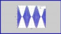
Data transmitted by a remote HC-12 transmitter is received and decoded as "AllAboutCircuits.com" by a local HC-12 receiver. Note the delay before the .com was transmitted, which might be due to the data handling of the Si4463 (see page 39 of the Si4463 datasheet) or to some aspect of the program running on the STM8S003FS.
The previous code, if uploaded to both boards, allows you to program both the local and remote transceiver at the same time.
Here are some other commands for your reference:
Valid Baud Rate Commands: AT+B1200, AT+B2400, AT+B4800, AT+9600, AT+19200, AT+38400, AT+57600, AT+115200
Valid Channel Commands: AT+C001, AT+C002, AT+C0xx, ... , AT+C099, AT+C100. Per its datasheet, if using multiple HC-12s on different channels, stagger adjacent channels at least five apart $$\frac{40\;\text{kHz}}{\text{1 channel}}\times\text{5 channels}=200\;\text{kHz}$$
Valid Transmit Power Commands: AT+P1 (-1 dBm), AT+P2 (2 dBm), AT+P3 (5 dBm), AT+P4 (8 dBm), AT+P5 (11 dBm), AT+P6 (14 dBm), AT+P7 (17 dBm), AT+P8 (20 dBm)
Return to default settings: AT+DEFAULT
Additional commands are available; refer to the user manual for more information.
Conclusion
The HC-12 is a capable transceiver with an impressive range (up to 1 km). It is satisfactory for most hobby and even some industrial applications. It is an important alternative to the very inexpensive, low-power, but short-range nRF24L01. Though a bit more expensive than the nRF24L01, its range and simplicity of use make the HC-12 an excellent choice for projects involving tracking. In the next article we will explore using the HC-12 in a GPS (Global Positioning System) application.
Give this project a try for yourself! Get the BOM.


Hi,
Is it possible to program the microcontroller on the HC12 board to directly read simple inputs such as switches or a voltage and send a signal by itself? Or maybe pull up or down a pin when certain command is received?
Great article!
Regards,
Willy
Hi @Wiky5 (Willy),
The short answer is possibly, but it’s not worth the time or energy required to attempt it. The microcontroller on the HC12 board is the Si4463 (datasheet is in the article), which has five GPIO pins, a couple of which might work as inputs / switches for your purpose—but there’s no real way to access them—this chip is the size of the nub on the end of an AA battery, and the manufacturers didn’t provide access to the extra pins on the circuitboard. Even if you manage to solder some wires to them, there’s a decent chance they have been tied to Vdd or Gnd.
It would be much simpler, and much quicker to add a microcontroller (for example, the ATTIny 85.
If you’d like to post your project idea in the Forums, I’m sure there are some site users that can help advise you. And if you do choose to do that, ping me and I’ll try to help too.
Thanks,
Mark