 Facebook
 Google
 GitHub
 Linkedin
Basic Binary Division: The Algorithm and the VHDL Code
This article will review a basic algorithm for binary division.
This article will review a basic algorithm for binary division.
Based on the basic algorithm for binary division we'll discuss in this article, we’ll derive a block diagram for the circuit implementation of binary division. We’ll then look at the ASMD (Algorithmic State Machine with a Data path) chart and the VHDL code of this binary divider.
Resources
Consider checking out related articles I've published in the past that may help you better understand this subject:
-
How to Write the VHDL Description of a Simple Algorithm: The Control Path
-
How to Write the VHDL Description of a Simple Algorithm: The Data Path
The Paper-and-Pencil Approach for Binary Division
To begin, consider dividing 11000101 by 1010.
Just as in decimal division, we can compare the four most significant bits of the dividend (i.e., 1100) with the divisor to find the first digit of the quotient. We are working with binary numbers, so the digits of the quotient can be either zero or one.
Since 1100 is greater than 1010, the first digit of the quotient will be one. The obtained digit must be multiplied by the divisor and the result must be subtracted from the dividend. Hence, we have
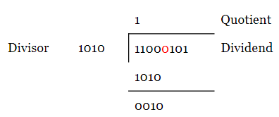
Now, we should write the next bit of the dividend (shown in red) to the right of the difference and continue the procedure just as we do in a decimal division. Hence, we obtain
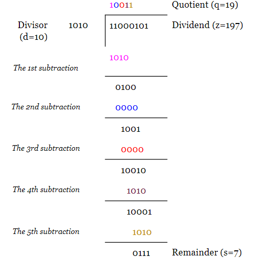
The above example shows the decimal equivalent of the parameters as well as the letters used to represent them. We can verify the calculations by evaluating $$z=q \times d+s$$ and that $$s < d$$.
To get a better insight into the implementation of the division algorithm, we rewrite the above example as:
First, the divisor is subtracted from the four most significant bits of the dividend. The result of this subtraction, i.e. 0010, is shown in blue.
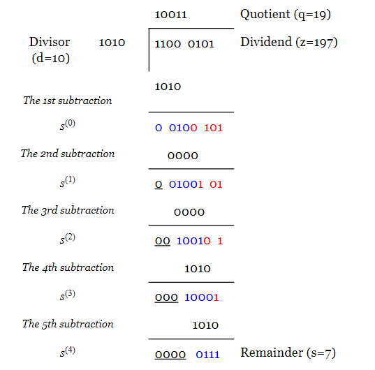
We can replace the four MSBs of the dividend with 0010 and obtain $$s^{(0)} = 0010 0101$$. The four LSBs of $$s^{(0)}$$, which are the same as the four LSBs of the dividend, are shown in red. Note that we no longer need the original dividend and we can replace it with $$s^{(0)}$$. From an implementation point of view, this means that we can use the register which was originally storing the value of the dividend to store $$s^{(0)}$$.
For the second subtraction, the divisor is shifted to the right by one bit. After subtraction, we obtain $$s^{(1)}=0010 0101$$. Again, the bits obtained from subtraction are shown in blue and the unaltered bits of $$s^{(0)}$$ are shown in red. We can now update the dividend register with $$s^{(1)}$$.
This procedure goes on until the final subtraction in which the LSB of the shifted divisor is aligned with the LSB of the dividend. After this final subtraction, the remainder will be less than the divisor.
Note that, as we proceed with the algorithm, the high order bits of the $$s^{(.)}$$ terms become zero (in this article, we’ll use $$s^{(.)}$$ to refer to the $$s^{(i)}$$ terms where $$i=0, 1, 3,$$ and $$4$$). This suggests that some bit positions of the dividend register will be no longer required. In the next section, we’ll see which bit positions are redundant. In the above example, the bit positions that can be discarded are underscored.
How to Implement the Division Algorithm?
As you can see from the above example, the division algorithm repeatedly subtracts the divisor (multiplied by one or zero) from appropriate bits of the dividend. Therefore, subtraction and shift operations are the two basic operations to implement the division algorithm.
After each subtraction, the divisor (multiplied by one or zero) is shifted to the right by one bit relative to the dividend. For the circuit implementation, we will shift the dividend to the left rather than shifting the divisor to the right (you can check that the latter requires more registers).
Besides, the numerical example shows that, as we proceed with the algorithm, some significant bits of the $$s^{(.)}$$ terms are no longer required and can be discarded. Which bit positions are we allowed to discard?
Obviously, to perform the subtraction, the bit position of the $$s^{(.)}$$ term right above the MSB of the divisor is required. For example, if we consider an arbitrary subtraction of the division algorithm as shown in Figure 1, the bit position denoted by $$s_{m+3}$$ is clearly required. What about the higher order bits of the $$s^{(.)}$$ term?
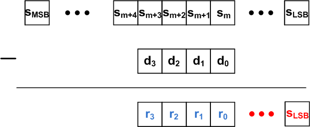
Figure 1
In Figure 1, the result of the subtraction is shown in blue and the bits of the difference that are the same as the $$s^{(.)}$$ term are shown in red. Similar to the decimal division, the difference ($$r_3r_2r_1r_0$$) is less than the divisor ($$r_3r_2r_1r_0 < d_3d_2d_1d_0$$). Hence, we have
$$s_{MSB} \dots s_{m+4} s_{m+3} s_{m+2} s_{m+1} s_m = r_3r_2r_1r_0 + d_3d_2d_1d_0 < 2 \times d_3d_2d_1d_0$$
This means that $$s_{m+4}$$ can be non-zero but all the bits to the left of $$s_{m+4}$$ are zero. Therefore, in each subtraction, we only need one extra bit of the $$s^{(.)}$$ term to the left of the divisor’s MSB. In the example of the previous section, the bit positions that can be discarded are underscored. This suggests that, as we proceed with the algorithm, we can use a smaller and smaller register to store the $$s^{(.)}$$ terms. Usually, the vacated locations of this register are used to store the quotient bits. This will be discussed in a minute.
A simplified block diagram for dividing an eight-bit number by a four-bit number is shown in Figure 2. The nine-bit register, $$z_8, \dots, z_0$$, stores the value of the dividend and the four-bit register, $$d_3, \dots, d_0$$, is used to store the divisor. $$z_8$$ is the extra bit which will be used to store the bit of the $$s^{(.)}$$ term to the left of the divisor’s MSB. At the beginning of the algorithm, this bit is set to zero.
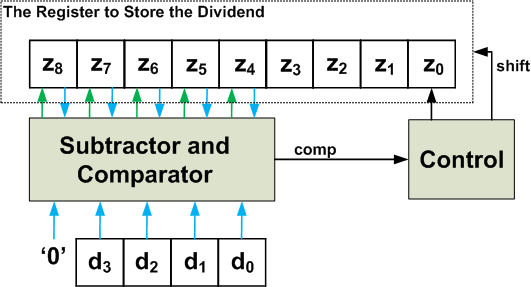
Figure 2
Proceeding with the algorithm, the content of the Z register will be updated (with subtraction result) and shifted to the left. After each shift operation, the LSB of the Z register will be empty. This empty memory element will be used to store the quotient bit just obtained.
Just like the paper and pencil approach, we can compare $$z_8z_7z_6z_5z_4$$ with $$d_3d_2d_1d_0$$ and decide whether the quotient bit must be zero or one. This is done by the “subtractor and comparator” block of Figure 2. When $$z_8z_7z_6z_5z_4 \geq d_3d_2d_1d_0$$, the “comp” signal will be logic high and the “control” unit will store the quotient bit, which is one, in the LSB of the Z register. When $$z_8z_7z_6z_5z_4 < d_3d_2d_1d_0$$, the obtained quotient bit will be zero and the LSB of the Z register will be zero.
Besides, the “control” unit must decide whether the five MSBs of the Z register needs to be updated or not. The “comp” signal can be used to make this decision as well. Based on our numerical example, we know that, when $$z_8z_7z_6z_5z_4 \geq d_3d_2d_1d_0$$, the five MSBs of the Z register must be updated with the difference $$z_8z_7z_6z_5z_4 - d_3d_2d_1d_0$$. When $$z_8z_7z_6z_5z_4 < d_3d_2d_1d_0$$, no update is required.
As discussed before, we will shift the content of the Z register to the left rather than shifting the divisor to the right.
Avoiding Overflow
During the last subtraction of the algorithm, the LSB of the dividend will be above the LSB of the divisor (see the 5th subtraction of the numerical example). This means that the value which was loaded to $$z_0$$ at the beginning of the algorithm will be at $$z_4$$ at the end of the algorithm. In other words, with the implementation of Figure 2, the division algorithm will involve a total of four shifts. We know that the memory locations vacated from these shifts will be used to store the quotient bits. Hence, the quotient must be less than or equal to $$1111_2 = 15_{10}$$. Considering the equation $$z=q \times d+s$$, we have
$$z = q \times d + s < (2^4-1) \times d + s = 2^4 \times d + s - d$$
Hence, $$z+(d-s) < 2^4 \times d$$. Since $$d-s$$ is a positive number, $$2^4 \times d$$ must be greater than $$z$$. In other words, at the beginning of the algorithm, we must have $$z_8z_7z_6z_5z_4 < d_3d_2d_1d_0$$, otherwise, the quotient will be greater than $$1111_2 = 15_{10}$$ and we cannot represent it in the vacated locations of the Z register.
As discussed above, the total number of shifts are known for the division algorithm. Therefore, we can use a counter to count the number of shifts and determine when the algorithm is finished. This counter will be reset to zero at the beginning of the algorithm.
The Division Algorithm
With the block diagram of Figure 2, we need to perform the following operations repeatedly:
- Load the dividend and the divisor to the Z and D registers, respectively. Reset $$z_8$$ to zero. Besides, set the value of the iteration counter to zero.
- If $$z_8z_7z_6z_5z_4 < d_3d_2d_1d_0$$, go to step 3 otherwise set a flag to indicate the overflow condition and end the algorithm.
- Shift the Z register to the left by one bit. The shift operation will vacate the LSB of the Z register. This empty memory location will be used to store the quotient bit obtained in the next step.
- Compare $$z_8z_7z_6z_5z_4$$ with $$d_3d_2d_1d_0$$:
(a) If $$z_8z_7z_6z_5z_4 \geq d_3d_2d_1d_0$$, set the LSB of the Z register to one and update the five MSBs of the Z register with the difference $$z_8z_7z_6z_5z_4 - d_3d_2d_1d_0$$.
(b) If $$z_8z_7z_6z_5z_4 < d_3d_2d_1d_0$$, set the LSB of the Z register to zero and keep the five MSBs of the Z register unaltered.
- Increase the value of the counter by one. If the counter is equal to four, end the algorithm otherwise go to step 3.
The ASMD Chart and the VHDL Code
Based on these steps, we can derive the ASMD chart of a 16-bit by 8-bit division as shown in Figure 3.
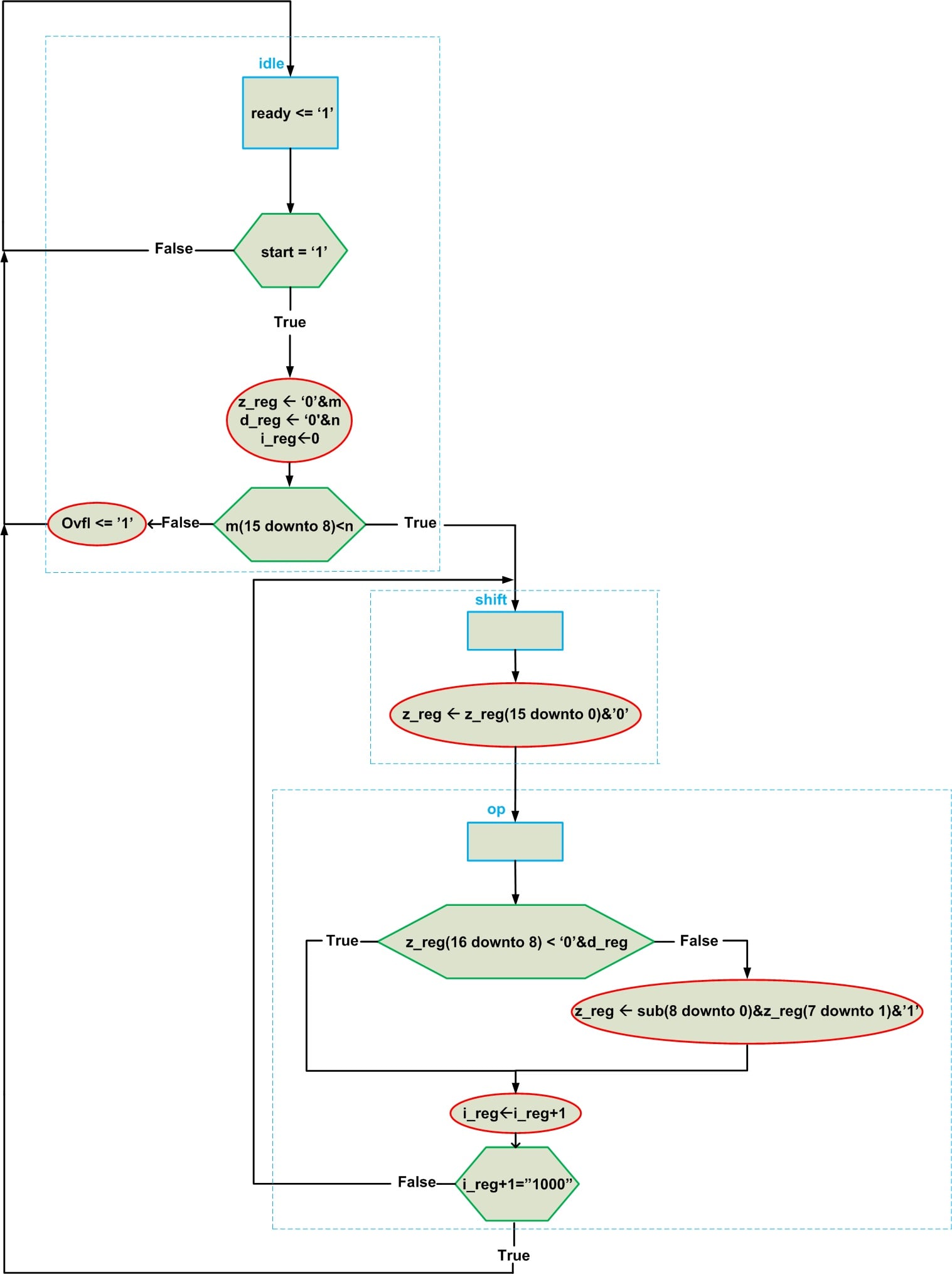
Figure 3
In this diagram, “start” is an input which tells the system to start the algorithm. When the calculations are finished, the “ready” output will be set to logic high to indicate the end of the algorithm. When facing an overflow, the “ovfl” output will go to high.
The “idle” state loads the z_reg and d_reg registers with the dividend (m) and the divisor (n) inputs, respectively. The iteration counter (i_reg) is also initialized in this state. The overflow condition will be checked and the next state will be chosen accordingly.
The “shift” state shifts the content of the z_reg register to the left by one bit. This will insert a zero to the right of the z_reg content. However, the value of this bit can change during the next phase of the algorithm.
The “op” state compares the registers. If the nine MSBs of the z_reg are greater than or equal to the content of d_reg, the LSB of the z_reg will be set to one and the nine MSBs of the z_reg will be updated with the subtraction result which is represented by “sub”. If the nine MSBs of the z_reg are less than the content of d_ref, we don’t have to change z_reg. Then the iteration counter will increase by one and we’ll check the number of shifts. If we have eight shifts the algorithm is finished and the next state is “idle”. If the number of iterations are less than eight, we should go back to the “shift” state and proceed with the rest of the algorithm.
To read more about deriving the ASMD chart, please see these two articles: How to Write the VHDL Description of a Simple Algorithm: The Data Path and How to Write the VHDL Description of a Simple Algorithm: The Control Path.
Now, having the ASMD chart, we can write the VHDL code of the algorithm:
1 library IEEE;
2 use IEEE.STD_LOGIC_1164.ALL;
3 use IEEE. NUMERIC_STD.ALL;

4 entity Divider is
5     Port (clk, reset : in STD_LOGIC;
6 	 start : in STD_LOGIC;
7 	 m : in  STD_LOGIC_VECTOR (15 downto 0);     -- Input for dividend
8            n : in  STD_LOGIC_VECTOR (7 downto 0);    -- Input for divisor
9            quotient : out  STD_LOGIC_VECTOR (7 downto 0);    -- Output for quotient
10          remainder : out  STD_LOGIC_VECTOR (7 downto 0);    -- Output for remainder
11	ready, ovfl : out STD_LOGIC);    -- Indicates end of algorithm and overflow condition
12 end Divider;

13 architecture Behavioral of Divider is

14            -- Type for the FSM states
15	  type state_type is (idle, shift, op);

16	-- Inputs/outputs of the state register and the z, d, and i registers

17	signal state_reg, state_next : state_type;
18	  signal z_reg, z_next : unsigned(16 downto 0);
19	  signal d_reg, d_next : unsigned(7 downto 0);
20	  signal i_reg, i_next : unsigned(3 downto 0);

21	-- The subtraction output
22	signal sub : unsigned(8 downto 0);

23 begin
24	  --control path: registers of the FSM
25	  process(clk, reset)
26	  begin
27		if (reset='1') then
28			state_reg <= idle;
29		elsif (clk'event and clk='1') then
30			state_reg <= state_next;
31		end if;
32	end process;

33	--control path: the logic that determines the next state of the FSM (this part of
34	--the code is written based on the green hexagons of Figure 3)
35	process(state_reg, start, m, n, i_next)
36	begin
37		case state_reg is
38			when idle =>
39				if ( start='1' ) then
40					if ( m(15 downto 8) < n ) then
41					state_next <= shift;
42					else
43					state_next <= idle;
44					end if;
45				else
46					state_next <= idle;
47				end if;

48			when shift =>
49				state_next <= op;

50			when op =>
51				if ( i_next = "1000" ) then
52					state_next <= idle;
53				else
54					state_next <= shift;
55				end if;

56			end case;
57		end process;

58	--control path: output logic
59	ready <= '1' when state_reg=idle else
60		    '0';
61	ovfl <= '1' when ( state_reg=idle and ( m(15 downto 8) >= n ) ) else
62		'0';

63	--control path: registers of the counter used to count the iterations
64	process(clk, reset)
65	begin
66		if (reset='1') then
67			i_reg <= ( others=>'0' );
68		elsif (clk'event and clk='1') then
69			i_reg <= i_next;
70		end if;
71	end process;

72	--control path: the logic for the iteration counter
73	process(state_reg, i_reg)
74	begin
75		case state_reg is
76			when idle =>
77				i_next <= (others => '0');
78
79			when shift =>
80				i_next <= i_reg;
81
82			when op =>
83				i_next <= i_reg + 1;
84		end case;
85	end process;


86	--data path: the registers used in the data path
87	process(clk, reset)
88	begin
89		if ( reset='1' ) then
90			z_reg <= (others => '0');
91			d_reg <= (others => '0');
92		elsif ( clk'event and clk='1' ) then
93			z_reg <= z_next;
94			d_reg <= d_next;
95		end if;
96	end process;

97	--data path: the multiplexers of the data path (written based on the register
98	--assignments that take place in different states of the ASMD)
99	process( state_reg, m, n, z_reg, d_reg, sub)
100	begin
101		d_next <= unsigned(n);
102		case state_reg is
103			when idle =>
104				z_next <= unsigned( '0' & m );
105
106			when shift =>
107				z_next <= z_reg(15 downto 0) & '0';

108			when op =>
109				if ( z_reg(16 downto 8) < ('0' & d_reg ) ) then
110					z_next <= z_reg;
111				else
112					z_next <=  sub(8 downto 0) & z_reg(7 downto 1) & '1';
113				end if;
114		end case;
115	end process;

116	--data path: functional units
117	sub <= ( z_reg(16 downto 8) - unsigned('0' & n) );

118	--data path: output
119	quotient <= std_logic_vector( z_reg(7 downto 0) );
120	remainder <= std_logic_vector( z_reg(15 downto 8) );

121 end Behavioral;
An ISE simulation for the above code is shown in Figure 4.
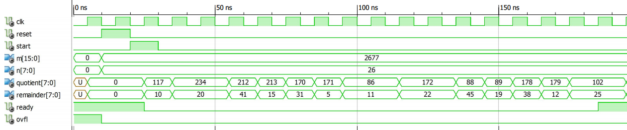
Figure 4
You can verify that when the “ready” output goes to logic high, we have $$m = n \times quotient + remainder$$.
Conclusion
This article examined a basic algorithm for binary division. We derived a block diagram for the circuit implementation of the binary division. We also examined the ASMD chart and the VHDL code of this binary divider.


Sir, I think you have made a mistake with your example division calculation. The results should be as shown here:
11111 quotient
—————
1010 ) 11000101 dividend
1010 reg’high = 1
——
1100
1010 reg’high = 1
——
1101
1010 reg’high = 1
——
1110
1010 reg’high = 1
——
1001
1010 reg’high = 1
——
0011
http://www.ee.unb.ca/cgi-bin/tervo/calc.pl?num=11000101&den=1010&f=d&e=1&m=1
I also think your VHDL code is rather longer than actually required, and can be illustrated with a single short ‘process’. The state machine perhaps confuses the simplicity of the implementation of the polynomial division mod 2, and can be excluded as managed by external housekeeping?