 Facebook
 Google
 GitHub
 Linkedin
Clean Power for Every IC, Part 3: Understanding Ferrite Beads
Ferrite beads used in conjunction with bypass capacitors can provide improved power-supply filtering and decoupling.
Ferrite beads used in conjunction with bypass capacitors can provide improved power-supply filtering and decoupling.
Articles That Provide Supporting Information
Previous Articles in This Series
- Clean Power for Every IC, Part 1: Understanding Bypass Capacitors
- Clean Power for Every IC, Part 2: Choosing and Using Your Bypass Capacitors
If Capacitance Is Not Enough
We concluded the previous article with a condensed set of recommendations for properly designing and laying out a power-supply bypass network that will store sufficient charge for long-term power-supply deviations and present low impedance to dominant noise frequencies. You can be confident that this approach will be more than adequate for most designs.
Nevertheless, the success of the capacitor-only approach does not mean that there is no room for improvement, and this is where a lesser-known decoupling component comes into play. If you feel that any ICs in your circuit are especially noise-sensitive (and therefore need additional filtering) or especially noisy (and therefore need additional decoupling from the power rail), you should explore the wonderful world of ferrite beads.
What’s in a Bead?
The simplest form of a ferrite bead is a conducting wire inserted through a hollow piece of ceramic material known as ferrite.

The electromagnetic properties of ferrite allow the material to influence the current flowing through the conductor. The precise nature of this influence depends in part on the type of ferrite (e.g., manganese-zinc vs. nickel-zinc), and the properties of a particular ferrite material can be further refined via the manufacturing process. In many surface-mount ferrite beads, the conductor is formed into a coil structure, with individual windings layered between ferrite sheets. Thus, the electrical characteristics depend also on the details of the winding construction.
Ferrite beads can be divided into two general categories: high-Q (aka resonant) beads, and low-Q (aka nonresonant) beads. High-Q beads are intended for applications that require high levels of resonance, such as oscillators and specialized filters. In the context of power-supply filtering, however, we need to minimize resonance (as discussed later in the article), so high-Q beads are out. For the remainder of this article, you can assume that any mention of ferrite beads refers to low-Q beads.
It’s Not an Inductor, Not a Capacitor, Not a Resistor. . .
In our attempt to understand ferrite beads, we can start by considering a first-order equivalent circuit and then translating this equivalent circuit into a generic plot of impedance vs. frequency.

The inductor is placed in the center as a reminder that the predominant response of a ferrite bead is inductive, i.e., impedance increases with frequency. However, at some point (generally somewhere between 30 and 500 MHz), the parallel capacitance begins to dominate the inductance, and impedance then decreases with frequency. The relatively small parallel resistance (say on the order of 100 Ω) reduces the resonance associated with the capacitor and inductor, such that the impedance levels off at the transition point instead of peaking in typical high-Q fashion. This response is evident in the following plot showing the measured impedance characteristics of a standard SMD ferrite bead manufactured by Wurth Electronics:
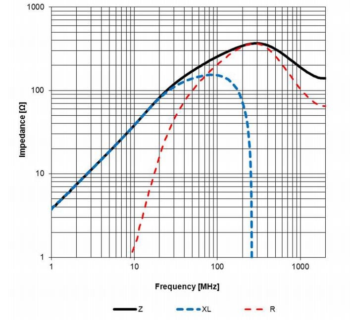
The black line indicates the overall impedance, which (though not shown in the plot) starts at Rseries, otherwise known as the bead’s DC resistance. It then increases linearly during the inductive frequency range, levels off at 300 MHz, and then begins to decrease before leveling off at 1.1 GHz.
The red and blue dotted lines indicate that the overall impedance is the result of two distinct elements, namely, inductive reactance (XL) and frequency-dependent resistance (R). This brings up an important point: the equivalent circuit given above is designed to replicate the frequency response of the bead—it does not convey the bead’s internal structure. The equivalent model is helpful for understanding how a ferrite bead’s impedance changes with frequency and for performing simulations, but it is primarily the ferrite material itself that determines the component’s impedance properties. This is important to understand because the equivalent circuit might distract you from one of the defining characteristics of ferrite beads: they actually dissipate high-frequency energy.
Noise In, Heat Out
Recall that ideal inductors and capacitors do not dissipate any energy; they merely store energy, either in a magnetic field (inductors) or an electric field (capacitors). A resistor, on the other hand, takes energy out of the circuit and dissipates it as heat. Ferrite beads, unlike inductors, are intentionally resistive at high frequencies. This is why the above plot has the red dotted line labeled “R”—from about 100 MHz to 1 GHz, the bead exhibits significant resistive impedance, not reactive impedance. Actually, some ferrite beads and ferrite-core inductors are almost identical in construction, except that the ferrite bead uses a more “lossy” ferrite material because the manufacturer wants the bead to dissipate rather than store high-frequency energy.
But why belabor this point? We belabor for two reasons. First, you cannot truly understand a ferrite bead until you have adequately pondered this fundamental distinction between an inductor and a bead. Second, this “lossy” characteristic makes the ferrite bead especially suitable for noise suppression. Why? Inductance can lead to resonance and ringing when high-frequency noise energy stored in the inductor interacts with capacitance elsewhere in the circuit. As we saw in the previous articles, ringing can become seriously problematic even when we are dealing only with parasitic inductance. We don’t want to exacerbate the resonance/ringing situation, and thus we opt for ferrite beads over inductors.
Choose Carefully
The key to maximizing the noise-suppression benefits of a ferrite bead is to ensure that the targeted noise frequencies fall within the bead’s resistive band—i.e., that portion of the frequency response where the resistive impedance dominates the reactive impedance. This means that you cannot simply look at the salient specs listed in a catalog or data sheet. For example, let’s say you expect a noise spike at 100 MHz due to a microprocessor clock signal. Digi-Key’s description for the Wurth part discussed above is the following:

And among the specifications you see this:

You might assume, based on this information, that the bead’s resistive band includes 100 MHz. In this case, you’d be right—as shown in the frequency response plot, this particular bead enters its resistive state at about 80 MHz.

However, there is still significant inductive reactance at 100 MHz, and clearly the bead would provide optimum performance at noise frequencies around 300 MHz.
Now, let’s say you were thinking about part number MMZ1608D121CTAH0 from TDK. The description and impedance spec are the following:


If you again assume that the bead is primarily resistive at 100 MHz, you will find yourself in a bit of trouble:

The plot reveals that 100 MHz is still very much within the inductive portion of the bead’s impedance curve. Based on the point at which the curve starts to level out, the resistive band begins at about 500 MHz, and the bead does not reach its optimum-noise-frequency point until 700 MHz. So if you choose this bead, not only is the impedance lower at the targeted noise frequency, but the type of impedance—namely, reactive—could make your circuit more susceptible to ringing or even severe oscillation on the power line.
Recap
Here we have explored some of the essential physical and electrical characteristics of ferrite beads, and we have seen that these components can be particularly effective in improving power quality when they are used to suppress noise frequencies that fall within their band of resistive-dominant impedance. In the next article, we will discuss specific techniques for incorporating ferrite beads into power-supply bypass networks.
Related Content


You may want to view my video that gives a practical review of ferrite bead characteristics and applications:
https://www.youtube.com/watch?v=81C4IfONt3o
My colleagues were looking for NJ AA302 earlier this week and were made aware of a web service that has lots of fillable forms . If others need to fill out NJ AA302 too , here’s http://pdf.ac/9FqVWU
Thanks useful information ....