Facebook
 Google
 GitHub
 Linkedin
Exponential and Piecewise-Linear Analysis in Forward-Conducting Diode Circuits
This article presents three analysis methods in which a diode is modeled using an exponential current–voltage relationship or a threshold-based linear relationship.
This article is a continuation of a short series on forward-conducting diodes. If you'd like to catch up before moving on, check out the first article on the exponential current–voltage relationship and the second on two diode circuit-analysis techniques.
Here, we'll discuss three more circuit analysis techniques you can use to characterize forward-conducting diode circuits.
The Piecewise-Linear Model
I personally have never used this technique, and it seems to me that the linearization of the diode’s conduction behavior is, overall, not significantly more accurate than the simpler constant-voltage-drop model explained in the previous article.
However, if you’re interested primarily in capturing the behavior of the diode in the transition region between non-conduction and full conduction, you might want to consider the piecewise-linear approach, since it gives you greater ability to approximate the true exponential behavior of the diode. Also, the piecewise-linear model replaces the diode with components that are compatible with the standard circuit-analysis procedures that we know so well, and consequently it is more versatile and straightforward than techniques that incorporate the exponential model.
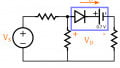
The schematic version of the piecewise-linear model is shown in the following diagram.
As you can see, we have a battery, just like in the constant-voltage-drop model, but we’ve added a resistor. The purpose of the battery is the same: it adds an offset that corresponds to a conduction threshold, and it creates a voltage drop. When the diode is in a conductive state, the resistor creates a linear relationship between forward voltage and forward current.
The following plot conveys the difference between the exponential model, the piecewise-linear model, and the constant-voltage-drop model.
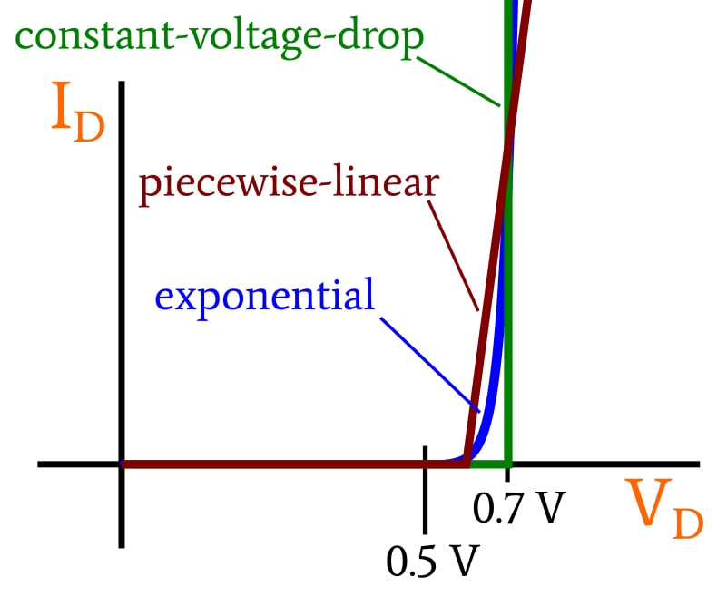
You can adjust the point at which the curve departs from the horizontal axis by changing the voltage assigned to the battery, and the slope of the line (in the conducting state) is equal to the reciprocal of the model’s resistance value.
If you know the specific current–voltage characteristics of the diode that you want to include in your circuit, you can adjust these two model parameters in an attempt to make the piecewise-linear representation as consistent as possible with the actual behavior of the diode.
The Exponential Model
As explained in the first article of this series, the I–V relationship of a diode is accurately captured by the exponential model. Thus, if we want results of very high accuracy, we must somehow combine the mathematical characteristics of the exponential model with the analysis techniques that we apply to other portions of a circuit. This can (in theory) be done graphically or by means of calculations.
The Graphical Approach
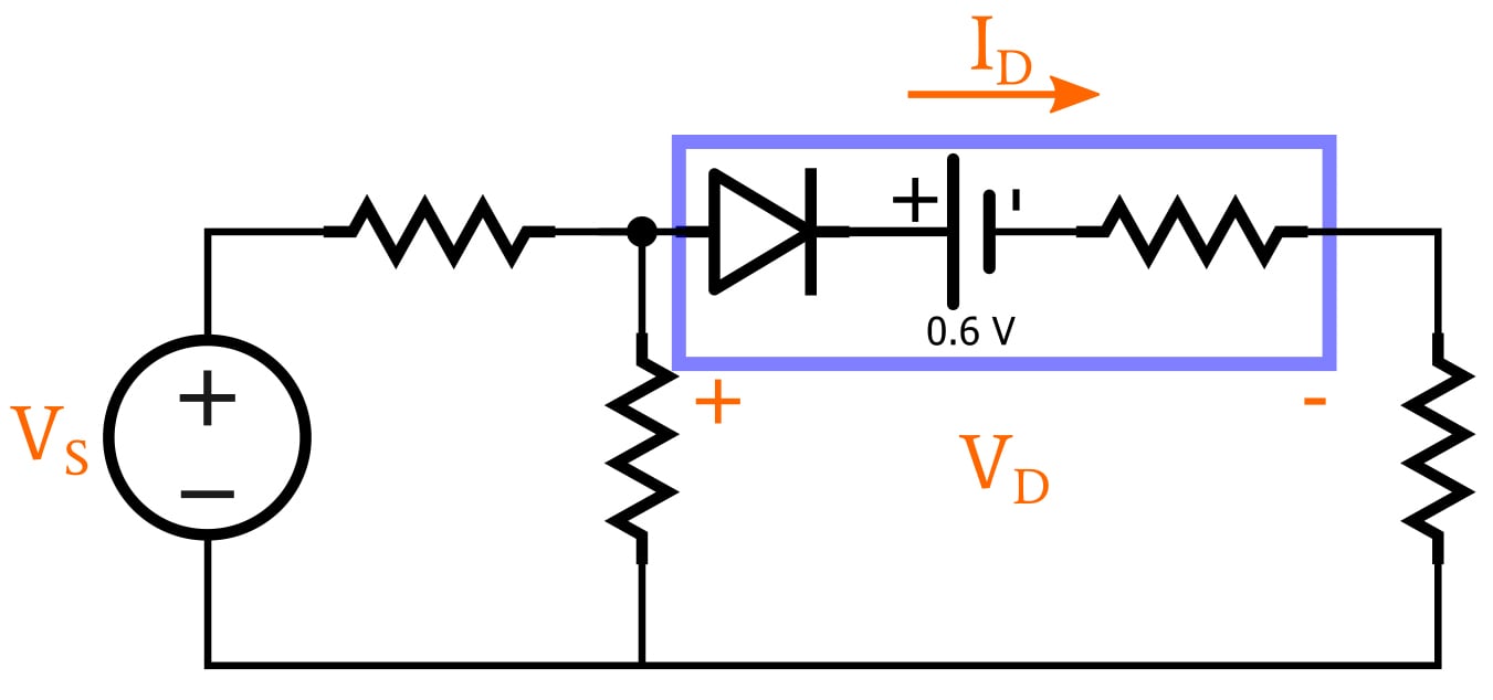
By combining a plot of a given diode’s I–V characteristic with a load line, we can find the operating point of a circuit. The diagram below shows a simple diode circuit and the corresponding graphical analysis.
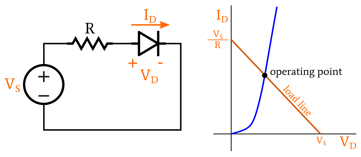
If you’re not sure what a load line is, you’ll definitely want to take a look at AAC’s Frequent Engineering Question (FEC) entitled How Is a Load Line Used in Circuit Design? And in fact, I’m not going to spend any more time on this topic, for two reasons: First, all the essential information is included in that FEC. Second, as far as I can tell, the graphical approach is mostly an exercise for students. There’s simply no reason why you would ever use this method to analyze a complex diode circuit.
The Iterative-Calculation Approach
While we’re on the topic of exercises for students, let’s briefly discuss the exponential-model-based iterative-calculation approach to solving diode circuits. That ponderous name refers to an equally ponderous analytical technique in which the diode equation is used to repeatedly calculate voltage and current values until the results of one iteration are not significantly different from the results of the previous iteration.
I suppose there are worse ways to spend your time, but I simply cannot justify any further explanation of a procedure that is uninteresting, time-consuming, error-prone, and obsolete.
Conclusion
It’s good to be aware of these techniques, and there may even be some situations in which you actually want to make use of them (though I can’t imagine that anyone these days would want to devote valuable time to the iterative method).
I have to acknowledge, however, that all three of these techniques are drudgery compared to the easiest and most accurate method of analyzing diode circuits: namely, SPICE simulation. It’s good to develop engineering intuition and exercise your circuit-analysis skills from time to time, but make sure that you’re saving most of your mental energy for the many problems that computers can’t solve.
Related Content