Facebook
 Google
 GitHub
 Linkedin
From Parallel to Serial and Back Again: Understanding SerDes
Serialization/deserialization circuitry, known collectively as SerDes, provides important benefits for digital communication systems, especially when high data rates are required.
In the early days of my engineering career, I assumed that parallel communication was usually preferable to serial communication. I appreciated the simplicity and efficiency of moving all 8 (or 16, or 32...) data bits simultaneously, with a control signal or two for handshaking and no need for elaborate synchronization schemes.
Before long, though, it became clear that prevailing digital communication protocols—UART, SPI, I2C, etc.—use a serial interface, and I also noticed that advanced protocols for specialized applications favor serial transfer. This is despite how microcontrollers and central processor units (CPUs) require parallel data for their internal storage, retrieval, and processing operations, meaning that serial communication involves additional serialization and deserialization hardware.
SerDes is a space-to-time-to-space conversion. Parallel data travels simultaneously but occupies different physical interconnections, and serial data shares the same physical space but occupies different moments in time (Figure 1).

Figure 1. An example diagram showing serialization and deserialization. Image used courtesy of Texas Instruments
With all of that in mind, let’s take a look at the limitations of parallel data transfer, and then I’ll discuss some prominent SerDes concepts.
Why is Serial Communication Preferred Over Parallel?
One of the more straightforward disadvantages of parallel transmission is the number of conductors involved. If you’re still working in the 8-bit world, using a bevy of interconnects might seem reasonable relative to the benefit of simple, simultaneous data transfer; however, the PCB layout task is increasingly inefficient and unmanageable as bus widths expand into the 16- or 32-bit range. The problem can become more acute when you have to move data not only from one component to another but from one PCB to another.
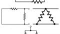
Additionally, each of these parallel data lines is not just a concern for the layout and cabling folks. Closely spaced wires or PCB traces (shown in Figure 2) are susceptible to crosstalk, especially with the high-energy logic transitions characteristic of digital signaling, and a larger group of conductors is more difficult to shield from ambient electromagnetic interference (EMI).

Figure 2. Traces have perfect electrical isolation when they are lines in a schematic, but on a real PCB, they’re capacitively coupled to nearby traces and plane layers.
With serial, a few interconnections suffice for transferring data words of any bit width, and you can reduce the likelihood of spurious logic transitions that degrade communication by corrupting data or necessitating retransmission.
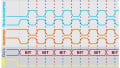
Parallel does, in theory, allow for faster data transfer, but even this advantage is more contingent than it initially appears. A longer trace or wire means that a signal will take more time to propagate from transmitter to receiver, and as data rates increase, it becomes more important to equalize delays throughout the bus by matching trace lengths. Trace-length matching for a high-speed, 32-bit bus is not trivial—and if I were doing the layout, it would be a very strong argument in favor of serialization/deserialization. Figure 3 shows an example of meandering, which can be helpful if you need to equalize trace length but not so helpful when you’re trying to minimize board area.

Figure 3. An example of meandering traces.
Another concern with high-speed parallel buses is excessive power consumption. Serialization can reduce power dissipation by converting standard logic signals into low-voltage differential signals.
What is SerDes? A SerDes Functionality and Features Overview
SerDes is a process involving two separate blocks of circuitry: In its rudimentary form, the serializer converts data represented by multiple simultaneous digital signals—output, for example, by a microprocessor or an ASIC—into a temporal sequence of logic levels traveling along one conductor. The deserializer converts this temporal sequence of logic levels back into a group of signals traveling simultaneously along multiple conductors.
Beyond this basic functionality, SerDes implementations have various details and additional features.
Multiple Serial Conductors
The parallel-to-serial conversion doesn’t necessarily compress multiple conductors into only one conductor. More generally, the goal of serialization is to significantly reduce the number of conductors.
First of all, a single serial communication line often requires two physical conductors because many serial interfaces, such as RS-485 and USB, use differential signaling. Furthermore, the optimal balance between throughput and interface complexity might require multiple serial channels. For example, in the block diagram below in Figure 4, from the datasheet for TI’s SN65LVDS95 LVDS serializer, 21-bit parallel data is converted into three separate streams of serial output.

Figure 4. Functional block diagram for the SN65LVDS95 serializer from the datasheet. Image used courtesy of Texas Instruments
Clock Multiplication
If a serializer receives parallel words at a certain frequency, it must increase the output bit rate in order to match the output word rate to the input word rate. Since serial transmission is much more amenable to high bit frequencies than parallel transmission, serialization need not entail any reduction in throughput. As shown in the diagram above, a phase-locked loop (PLL) can be used to multiply the input clock according to the compression factor achieved in the parallel-to-serial conversion.
Tx/Rx Synchronization
As with any digital communication interface, SerDes requires some synchronization mechanism to ensure that the receiver knows how to sample and parse the incoming logic levels. Some systems, including the one depicted in the diagram above, send a clock signal along with the data.
It is also possible for the deserializer to derive synchronization from the incoming serial bit stream: a PLL can lock onto the bit stream and produce a sampling clock. However, the PLL will drift if the input signal has insufficient transition density. For example, a sensor signal might saturate at the positive supply rail and be digitized and serialized into a long sequence of logic high bits. To prevent problems associated with low transition density, you can combine your SerDes system with a standard (such as 8b/10b) or homebrew encoding scheme.
Transmission Media
Transferring parallel data as serial data gives you physical transmission options that otherwise wouldn’t be feasible. Even when all your signals stay on the same PCB and everything is routed with ordinary traces, serialization can greatly facilitate board layout. If you’re moving data from board to board, module to module, or system to system, you may prefer to use a coaxial cable or an optical link. If you have serialized data, you’re in a good position to upgrade from ordinary wires to coax or fiber optics.
Reaping the Benefits of SerDes
SerDes has become indispensable for digital electronics. The extremely high data rates required for video interfaces, telecom interconnections, and various other applications could not be similarly achieved using parallel transfer.
Feel free to leave a comment and tell us how you’ve incorporated serialization/deserialization into your designs.