 Facebook
 Google
 GitHub
 Linkedin
How to Generate a Sine Wave: The Phase-Shift Oscillator
This article, part of AAC’s Analog Circuit Collection, explains a fairly straightforward circuit that can be used as part of an analog oscillator.
This article, part of AAC’s Analog Circuit Collection, explains a fairly straightforward circuit that can be used as part of an analog oscillator.
Sinusoidal signals are one of the pillars of modern electronics. It is somewhat surprising, then, that they are not exactly easy to create.
One of my preferred methods is to generate a square wave at the desired frequency and then filter out the harmonic components; this approach is described in a sound synthesizer article that I wrote a couple years ago. This technique is effective and not overly complicated, but it is not exactly an efficient use of resources, at least in a theoretical sense. It hardly matters nowadays when microcontrollers and their required development tools are widespread and inexpensive.
Still, there is something dissatisfying (and also intellectually limiting) about using so much digital circuitry driven by a high-frequency digital clock signal when it is possible to create an analog oscillator using one op-amp, some passives, and two diodes.
From Amplifier to Oscillator
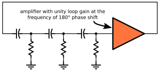
The circuit that I’m referring to is built around something called a phase-shift oscillator, which is a pleasantly simple way of forcing a circuit to produce sustained sinusoidal oscillations. In the purely theoretical world, you can make a phase-shift oscillator with one amplifier, three resistors, and three capacitors:
If you have read my article on negative feedback amplifiers, you know that they can become oscillators if phase shift causes the negative feedback to become positive feedback.
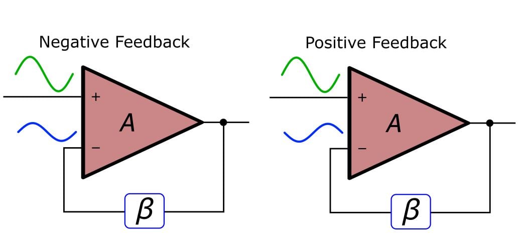
The more detailed explanation is as follows: The loop gain of a negative-feedback amplifier circuit is the open-loop gain of the amplifier (denoted by A) multiplied by the feedback factor, called β. The loop gain can have a frequency response, and if this frequency response involves a phase shift that reaches 180°, you might have an oscillator on your hands. I say “might” because there is another criterion: the loop gain must be greater than unity for the frequency at which the phase shift is 180° (call it f180). If indeed the loop gain reaches 180° of phase shift when the gain is greater than unity, the amplifier will oscillate.
Usually, this oscillation thing is a nuisance, but when you’re designing a phase-shift oscillator, the whole point is to achieve 180° phase shift with gain greater than unity. As you know, one RC filter creates one pole, and each pole contributes 90° of phase shift. Two poles theoretically give us 180°, but only as the frequency extends out toward infinity. That’s why we have three RC sections in the phase-shift oscillator: three poles can give us 180° of phase shift at a reasonable frequency. Then all we need to do is incorporate these three filters into a feedback system that has greater-than-unity loop gain at f180.
Theory vs. Reality
It turns out that generating stable, sustained oscillations is far more difficult than generating oscillations that gradually (or not so gradually) diminish toward zero amplitude or increase toward saturation. In the mathematical realm, we could design a circuit whose loop gain is exactly unity at f180, and this would result in sustained oscillations.
In the reality realm, that sort of precision is impossible, and it is laughably impossible when you consider the constant environmental and operational variations that characterize real-world systems. The loop gain will always be greater than or less than unity. If it’s greater than unity, the oscillations will increase until the amplifier saturates; if it’s less than unity, the oscillations will fade away.
Thus, a phase-shift oscillator needs a limiting circuit—and how convenient that I recently wrote an article on a simple-but-effective limiter topology!
The Low-Pass Variant
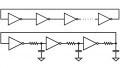
The circuit diagram shown above has three high-pass filters. When I said that you can make an “analog oscillator using one op-amp, some passives, and two diodes,” I was referring to a circuit that combines this high-pass oscillator and a limiter. I have no doubt that this is a great circuit, but I don’t like it because it’s not intuitive, or at least it’s less intuitive than I want it to be.
So, I created an alternative that is built around three low-pass filters. I’m not sure how the performance compares but my version seems to work—and, in my opinion, it is easier to analyze and understand.
Here is the phase-shift oscillator portion of the overall circuit:
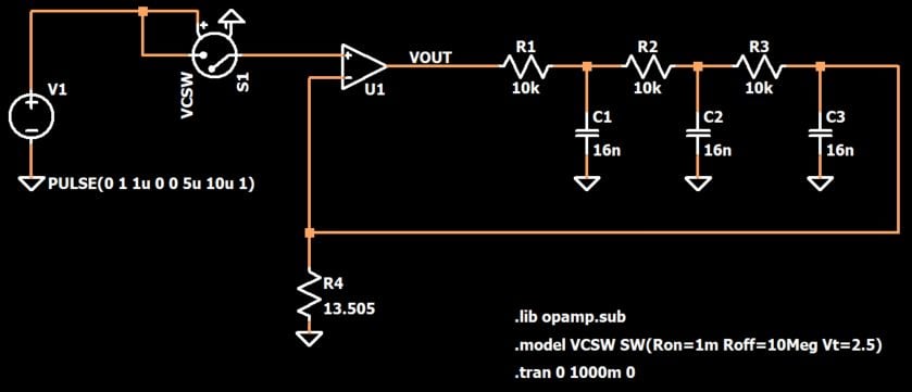
As you can see, the op-amp is configured like a standard feedback amplifier: the input is applied to the non-inverting terminal and the feedback signal is subtracted from the input by applying it to the inverting terminal.
The low-pass filters are included in the feedback network, where they introduce plenty of destabilizing phase shift into the loop gain. The magnitude of the loop gain is fine-tuned by adjusting the value of R4. If you set R4 to the perfect value, you’ll get stable oscillations.
Starting Oscillation
Real circuits always have noise or transients that provide the “jumpstart” needed to initiate oscillation. SPICE simulations have no such imperfections—I suppose this is one of the very few situations in which a SPICE simulation is actually less convenient than building a physical circuit.
So, instead of relying on noise to do the job, we will intentionally inject some broadband energy by applying a pulse through a voltage-controlled switch. When the pulse is active, the switch is on such that the pulse voltage can enter the circuit and stimulate oscillation. When the pulse is inactive, the switch is an open circuit and the voltage source no longer has any effect.

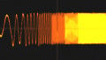
The following plots show the response with three different values of R4: one is too high, one is too low, and one is just right.


Conclusion
In this article, we looked at two different versions of a phase-shift oscillator and we discussed the need for a limiter in real-world implementations.
At this point, the circuit may still be a bit of a mystery to you, but that will be remedied in the next article, where we will analyze the frequency response in detail and also complete the circuit by adding a limiter. If you want to experiment with this circuit in the meantime, feel free to download my LTspice schematic file by clicking on the orange button.
Related Content


This can also be done with a tank circuit and an OpAmp, which keeps powering the tank circuit in sync with the phase, so it will grow from a week signal to a stable, perfect sine wave and maintain it.
The high-pass variant is the one usually given as an example in texts yet that makes no sense to me as harmonics caused by any distortion will be passed through the filter more readily. The low-pass version will surely produce less distortion? I’ve never actually investigated this so please correct me if I’m wrong.
It is, however, rather more difficult to set up the correct DC conditions (especially for a transistor circuit) using the low-pass, which may be the reason most authors prefer the high-pass. A large-value capacitor at the end of the chain is all that’s needed resolve any issue.