Facebook
 Google
 GitHub
 Linkedin
How to Low-Pass Filter a Square Wave
This article, part of AAC’s Analog Circuit Collection, presents a circuit that is a good choice when you need to remove high-frequency noise from a digital signal.
This article, part of AAC’s Analog Circuit Collection, presents a circuit that is a good choice when you need to remove high-frequency noise from a digital signal.
Filters are usually discussed in the context of analog signals: removing noise from audio, channel selection or image rejection in RF systems, line-frequency rejection in medical devices, anti-aliasing in ADC circuits, and so forth. However, digital signals can be affected by noise as well, and though digital communication is inherently more noise-tolerant than analog communication, there may be times when you would like to clean up a digital waveform at some point in the signal chain.
One possible application occurs to me because I mentioned it in a recent article about how to implement Manchester encoding. I presented a basic circuit (just an XOR gate) that can be used to turn a normal digital signal into a Manchester signal, but I also pointed out that the XOR approach is susceptible to spurious transitions. I then suggested that in some cases a system could overcome these (higher-frequency) spurious transitions by means of a low-pass filter.
Another situation in which you might want to low-pass filter a digital signal is when you’re using SPI, I2C, or UART to transfer data between different portions of a robot. Transient noise generated by electromechanical devices or high-current drive circuitry might be serious enough to produce an occasional (or not so occasional) error in your digital communications—I’m imagining something like a UART wire that is connected between two separate PCBs and that must pass perilously close to a brushed DC motor. You might be able to suppress this noise via filtering, especially if your data-transfer requirements allow you to use a low data rate.
Avoiding Distortion
You may be wondering why you need some sort of special filter for a digital signal. What’s so different about low-pass filtering a digital waveform compared to low-pass filtering an analog waveform?
Well, it all goes back to the Fourier transform. If you live in the frequency domain, a digital waveform is not actually a digital waveform. It’s a combination of a long (theoretically infinite) sequence of sinusoids with different frequencies and different amplitudes. When these sinusoids are all perfectly aligned, the result is a normal square (or rectangular) waveform. When they are not aligned, however, you end up with a distorted lumpy thing that is not really a square wave, but also certainly not a sine wave.
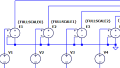
Let’s look at an example. The following circuit is a fourth-order Butterworth low-pass filter (I used the Analog Devices “filter wizard” to generate the component values):

Click to enlarge.
Here’s the frequency response:

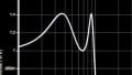
If I use this circuit to filter a 10 kHz square wave, this is the result:

The problem here is that the Butterworth filter does not have a linear phase response—in other words, the phase shift changes in such a way that different frequencies experience different temporal delays. Thus, the frequency components in the square wave don’t stay aligned as they move through the filter, and the end result is the overshoot/undershoot that you see on the rising/falling edge.
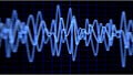
The overshoot present in the above plot is not terrible, but the overall appearance of the waveform deteriorates as the period decreases:

Note also that the ringing will become more severe as the order of the filter increases.
The Bessel Filter
We can solve this problem by using a Bessel filter. In the introduction I said that this article would present a “circuit,” but that’s imprecise because the Bessel circuit itself (i.e., the arrangement of components) is not different from a Butterworth circuit or a Chebyshev circuit. What turns a second-order filter stage into a Bessel (or Butterworth, or Chebyshev) filter are the component values, which are calculated so as to create the frequency response corresponding to these filter types. It would be a good intellectual exercise to determine these component values using filter tables, but in the “real world” of goal-oriented engineering, it is hard to compete with software such as the Analog Devices tool mentioned above.
The Bessel filter is optimized for linear phase response, which makes it ideal for minimizing ringing in digital signals. Ringing, overshoot, distortion, settling time—these are all terms that we can use when referring to the alteration of a filtered digital waveform, but it’s important to remember the true cause of this alteration: nonlinear phase response, which creates temporal separation between the Fourier frequencies that make up the square wave.
The following circuit has four poles, like the previous one, and the cut-off frequency is the same. The component values, however, are selected so as to create a Bessel response instead of a Butterworth response.

Click to enlarge.
Here is the Bode plot:

The following plot includes time-domain waveforms for both the Butterworth and the Bessel filters; you can see that the Bessel filter greatly reduces the distortion.
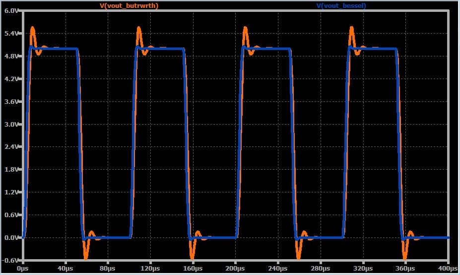
Click to enlarge.
Conclusion
We discussed the concept of low-pass filtering for digital signals, and then we looked at the undesirable effects produced by a filter that does not have a linear phase response. We concluded by introducing the Bessel filter, which is optimized for linear phase response and which clearly can reduce the amount of ringing in a time-domain waveform. In this article we used the Sallen–Key topology for our second-order filter stages, but it is also possible to create Bessel filters using only passive components.
Feel free to download my LTspice schematic by clicking on the orange button. This will save you some time if you want to test and analyze a customized Bessel filter.