 Facebook
 Google
 GitHub
 Linkedin
Understanding the Amplifier Offset Voltage and Output Swing in Resistive Current Sensing
How does an amplifier's input offset voltage impact the accuracy of a current sense resistor's measurement? And how does amplifier output swing affect your shunt resistor value? Learn this and more in this technical article.
In previous articles, we discussed that op-amp-based amplifiers, as well as purpose-built current sense amplifiers, can be used to gain up the voltage across a current sense resistor. These amplification stages are not ideal and can introduce an error in our measurement.
In this article, we’ll discuss how the amplifier input offset voltage can affect the accuracy of our measurement. We’ll also see that the amplifier output swing can be a key factor when choosing the shunt resistor value.
Input Offset Voltage
Ideally, the output of a differential amplifier should be at zero volts when its both inputs are exactly at the same potential. However, in reality, the output goes to zero volts when there is a small voltage difference between the inputs. This non-ideality originates from the inherent mismatch between the components inside the amplifier.
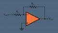
The voltage that must be applied between the input terminals of the amplifier to bring its output voltage to zero volts is called the input offset voltage. To model this non-ideal effect, we can place a voltage source in series with one of the amplifier inputs and assume that the amplifier is ideal and has zero offset voltage. This is shown in Figure 1.

Figure 1
In Figure 1, the circuitry inside the gray box represents an integrated current sense amplifier. Since the offset voltage is modeled by the external voltage source Voffset, the circuitry inside the gray box is assumed to have an offset voltage of 0V, i.e. with VA = VB we have Vout = 0. The polarity of the offset voltage can be either positive or negative.
Error From the Amplifier Offset Voltage
Consider the high-side current sensing diagram shown in Figure 2.

Figure 2
The amplifier actually senses the voltage between nodes A and B. Assuming a differential gain of Ad for the amplifier, we have:
\[V_{out} = A_d(V_A - V_B) = A_d(V_{offset} + V_{shunt})\]
If Voffset is comparable with Vshunt, the error can be significant. For example, with Voffset = Vshunt, the error is 100%, as calculated below:
\[Percentage~Error = \frac{V_{sensed} - V_{shunt}}{V_{shunt}} \times 100\% = \frac{(V_{offset} + V_{shunt}) - V_{shunt}}{V_{shunt}} \times 100\% = 100\%\]
The error is maximized when Vshunt is at its minimum. Hence, in order to find the worst-case error from the offset voltage, we should consider the minimum value of the load current Iload.
How can we reduce this error?
For a given load current range, we can either increase the shunt resistor value to have a larger Vshunt and/or use an amplifier with a smaller offset voltage.
However, it should be noted that increasing the shunt resistor value increases the power dissipated by the resistor. Additionally, higher wattage resistors are more expensive and require a larger board area.
Determining the Value of the Shunt Resistor
As discussed above, there is a trade-off between the accuracy on the low end of the measurement range and the power dissipated by the shunt resistor. The accuracy can be maximized by choosing a large shunt resistor.
However, in a high-current precision application, the power dissipated by the current sense resistor can limit the maximum resistor value that can be used. In this case, we can choose the maximum value of Rshunt based on its maximum allowable power dissipation. If the maximum power dissipation that is budgeted for the shunt resistor is Pmax, the maximum shunt value can be calculated by:
\[R_{shunt} \leq \frac{P_{max}}{I_{load,~max}^2}\]
The maximum value of Rshunt can also be limited by the amplifier output swing to the positive rail. The swing limitation of an amplifier depends on the supply voltage used to power the amplifier as well as the output stage of the amplifier.
Although the output of a rail-to-rail amplifier can get very close to the supply rails, it cannot actually reach them. Even with a rail-to-rail amplifier, the output swing might be limited to hundreds of millivolts away from supply rails, depending on the technology.
The output swing limitations of an amplifier also depend on the current level flowing through the output stage. The amplifier datasheet must be consulted to determine the available swing at the amplifier output.
If Vout, max is the maximum voltage at which the amplifier output stage remains in its linear region of operation, then the maximum shunt value can be calculated by:
\[R_{shunt} \leq \frac{V_{out,~max}}{I_{load,~max}A_d}\]
Equation 1
We can also find the lower limit of Rshunt by taking into account the output swing to the negative rail. If Vout, min is the minimum output voltage that guarantees the amplifier to be in its linear region of operation, we can find the minimum value of Rshunt as:
\[R_{shunt} \geq \frac{V_{out,~min}}{I_{load,~min}A_d}\]
Equation 2
Example Shunt Resistor Value Calculation
Assume that we need to monitor a load current between 40 mA and 1 A. The amplifier has a gain of 50, Vout, max = 4.9 V and Vout, min = 100 mV. Assuming that the application has not limited the power dissipated by the shunt resistor, what value of Rshunt do we need?
To minimize the error from the amplifier offset voltage, we should choose the maximum value for Rshunt. Applying Equation 1, we obtain:
\[R_{shunt} \leq \frac{V_{out,~max}}{I_{load,~max}A_d} = \frac{4.9}{1 \times 50} = 98~m\Omega\]
Using Equation 2, we can find the minimum value of Rshunt as:
\[R_{shunt} \geq \frac{V_{out,~min}}{I_{load,~min}A_d} = \frac{0.1}{0.04 \times 50} = 50~m\Omega\]
The largest standard value in this range should be chosen to minimize the offset error. After choosing the appropriate value of Rshunt, we can evaluate the offset error by applying the following equation:
\[Percentage~Error = \frac{(V_{offset} + V_{shunt}) - V_{shunt}}{V_{shunt}} \times 100\% = \frac{V_{offset}}{R_{shunt} \times I_{load,~min}} \times 100\%\]
To reduce the error to the desired level, we need to choose an amplifier with sufficiently low input offset voltage.
I would like to attract your attention to a subtle point here. Considering the output swing limitation of an amplifier, is there a contradiction in the offset voltage definition?
The offset voltage is defined as the differential voltage that must be applied between the input terminals of the amplifier to bring its output voltage to zero volts; however, the output of a single-supply amplifier cannot really swing to the ground potential.
These details can be important when measuring very small currents.
Determining the Offset Voltage of a Single-Supply Amplifier
As discussed above, when the negative rail of an amplifier is tied to ground, its output can only get close to the ground potential. This is illustrated in Figure 3.

Figure 3
In this figure, the blue curve shows the amplifier output versus the differential voltage applied to the input.
For very small values of the differential input, the output voltage reaches Vout, min. Since the output doesn’t go below Vout, min, we cannot directly measure Voffset.
Instead, we can fit a line to the transfer function curve in the linear region of operation and consider the intersection of this line with the horizontal axis as the input offset voltage of the amplifier. You can imagine that if the amplifier was ideal, the dotted line would go through the origin.
We can now find the equation of the dotted line and determine the offset voltage. If the output is at Vout1 and Vout2 when the input is respectively at Vdiff1 and Vdiff2, we can find Voffset as:
\[V_{offset} = V_{diff1} - \frac{(V_{diff2} - V_{diff1})}{(V_{out2} - V_{out1})} \times V_{out1}\]
Can We Use a Single-Supply Amplifier for Measuring Very Small Currents?
Using a single-supply amplifier to measure near-zero load currents can introduce an unacceptable error due to the output swing limitations of the amplifier. This is shown in Figure 4.

Figure 4. Image courtesy of Texas Instruments.
To circumvent this problem, the reference design “0-1A, Single-Supply, Low-Side, Current Sensing Solution Reference Design” from Texas Instruments uses the LM7705 inverting charge pump to generate a -0.23V supply for the negative rail of the amplifier. This reference design is based on a discrete solution that uses an op-amp along with external gain-setting resistors as shown in Figure 5.

Figure 5. Image courtesy of Texas Instruments.
According to the mentioned reference, the negative supply must be at least 100 mV less than the system ground to make sure that the amplifier exhibits a linear output down to 0 V.
Another technique that enables measuring small currents is shown in Figure 6.

Figure 6
In this case, Vref is used to add a DC value to the output voltage. The transfer function will change to:
\[V_{out} = A_d(V_A - V_B) + V_{ref}\]
This technique can also be used to sense bidirectional load currents (positive and negative load currents) by means of a single-supply amplifier. Depending on the desired current range, the appropriate value for Vref should be chosen.
Conclusion
The amplifier input offset voltage affects the accuracy on the low end of the measurement range. To reduce this error, we should maximize the shunt resistor value.
However, the shunt value can be limited by the budgeted power and the available swing at the amplifier output. Output swing limitations can also introduce error when measuring near-zero load currents.
To see a complete list of my articles, please visit this page.
Related Content


It took me a hot minute to figure out the current Iload was being multiplied by the gain in equations 1 & 2! I was like that result should be divided by the gain…until I realized it was. In case anyone else is confused, it’s because (Vout / iLoad) / Ag simplifies to Vout/(iLoad x Ad). Just a bit confusing at first glance.