Facebook
 Google
 GitHub
 Linkedin
Understanding Low-Pass Filter Transfer Functions
This article provides some insight into the relationship between an s-domain transfer function and the behavior of a first-order low-pass filter.
This article provides some insight into the relationship between an s-domain transfer function and the behavior of a first-order low-pass filter.
Lately, I’ve been doing quite a bit of writing on the topic of filters, and though I’ve been focusing on practical considerations, I feel the need to explain some important theoretical concepts for the benefit of those who would like to more thoroughly understand and analyze the behavior of analog filters. Nowadays everyone has access to software tools that make sophisticated filter design relatively painless, but I don’t think it’s wise to completely ignore a mathematical foundation simply because it is not strictly necessary for the completion of many real-life design tasks.
The s-Domain
The response of a filter can be expressed by an s-domain transfer function; the variable s comes from the Laplace transform and represents complex frequency. For example:
$$T(s)=\frac{K}{1+(\frac{s}{ω_O})}$$
This transfer function is a mathematical description of the frequency-domain behavior of a first-order low-pass filter. The s-domain expression effectively conveys general characteristics, and if we want to compute the specific magnitude and phase information, all we have to do is replace s with jω and then evaluate the expression at a given angular frequency.
You may be wondering where K and ωO come from—you’ve probably never seen a circuit diagram that has component values expressed in terms of K and ωO. The idea here is that K and ωO are like portions of a template, and in the next section we’ll look at the relationship between the template and a circuit diagram.
s-Domain Circuit Analysis
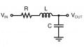
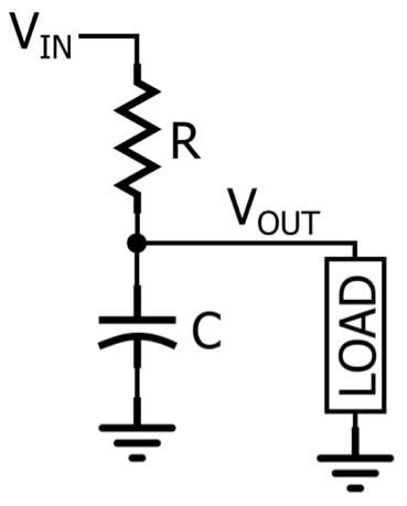
An RC low-pass filter is a frequency-dependent voltage divider. In an s-domain analysis, the impedance of a resistor is R and the impedance of a capacitor is $$\frac{1}{sC}$$.
$$\frac{V_{out}}{V_{in}}=\frac{\frac{1}{sC}}{\frac{1}{sC}+R}=\frac{1}{1+sRC}$$
If we compare this expression to the standardized transfer function, we can see that K = 1 and $$\omega _{O} = \frac{1}{RC}$$. The convenience of using the standardized form becomes clear once you know what K and ωO represent: K is the circuit’s gain at DC, and ωO is the cutoff frequency. Thus, by comparing the circuit’s transfer function to the standardized transfer function, you can immediately formulate expressions for the two defining characteristics of a first-order low-pass filter, namely, the DC gain and the cutoff frequency.
Another standardized form of a first-order low-pass transfer function is the following:
$$T(s)=\frac{a_{O}}{s+\omega _{O}}$$
We can fit the circuit’s transfer function into this template if we divide the numerator and denominator by RC:
$$T(s)=\frac{1}{1+sRC}\rightarrow \frac{\frac{1}{RC}}{s+\frac{1}{RC}}$$
Thus, $$a_{O}=\frac{1}{RC}$$ and $$\omega _{O}=\frac{1}{RC}$$. This form doesn’t directly give us the DC gain, but if we evaluate the standardized expression for s = 0, we have
$$T(s=0)=\frac{a_{O}}{\omega _{O}}$$
This means that the DC gain of our RC filter is $$(\frac{1}{RC})/(\frac{1}{RC}) = 1$$, and a DC gain of unity is exactly what we expect from a passive low-pass filter.
Understanding Cutoff Frequency
We’ve seen that ωO in the standard transfer function represents the cutoff frequency, but what is the mathematical basis of this fact?
First, let’s convert the standard s-domain transfer function into the equivalent jω transfer function.
$$T(s)=\frac{K}{1+\frac{s}{\omega _{O}}}\rightarrow T(j\omega )=\frac{K}{1+j\frac{\omega }{\omega _{O}}}$$
Now let’s evaluate the expression at the cutoff frequency.
$$T(j\omega =j\omega _{O})=\frac{K}{1+j\frac{\omega _{O}}{\omega _{O}}}=\frac{K}{1+j}$$
The denominator is a complex number so the magnitude will be
$$\left | T(j\omega =j\omega _{O}) \right |=\frac{K}{\sqrt{1^{2}+1^{2}}}=\frac{K}{\sqrt{2}}$$
Since K is the DC gain, a very-low-frequency input signal with an amplitude of one volt will lead to an output signal that has an amplitude of K volts. If the input frequency increases to ωO radians per second, the output amplitude will be $$\frac{K}{\sqrt{2}}$$. The factor $$\frac{1}{\sqrt{2}}$$ corresponds to –3 dB, and as you probably know, another name for the cutoff frequency is the –3 dB frequency.
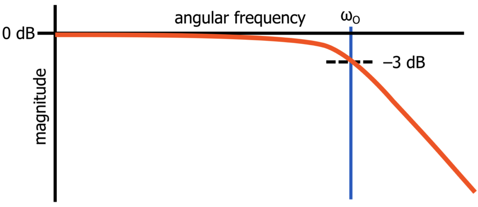
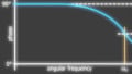
This is the shape of the magnitude response of a first-order passive low-pass filter when it is plotted as magnitude in dB versus logarithmic frequency.
This straightforward transfer-function analysis has demonstrated clearly that the cutoff frequency is simply the frequency at which the filter’s amplitude response is reduced by 3 dB relative to the very-low-frequency amplitude response.
Cutoff Frequency and Phase Shift
The cutoff frequency of a low-pass filter has a special significance also with respect to the circuit’s phase response. If we write a complex number in the form x + jy, we calculate the phase as follows:
$$\theta =tan^{-1}(\frac{y}{x})$$
Thus, the overall phase response of our RC low-pass filter is
$$\theta (\omega )=-tan^{-1}(\frac{\frac{\omega}{\omega _{O}}}{1})=-tan^{-1}(\frac{\omega }{\omega _{O}})$$
If we evaluate this expression at ω = ωO, the phase shift is
$$-tan^{-1}(\frac{\omega _{O}}{\omega _{O}})=-tan^{-1}(1)=-45°$$
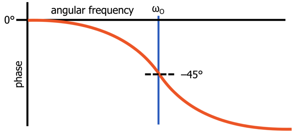
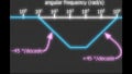
This is the shape of the phase response of a first-order passive low-pass filter when the phase shift is plotted versus logarithmic frequency.
The maximum phase shift generated by a first-order low-pass filter is 90°, so this analysis tells us that the cutoff frequency is the “center” of the circuit’s phase response—in other words, it is the frequency at which the filter generates half of its maximum phase shift.
Conclusion
I hope that you have enjoyed this brief introduction to s-domain concepts and transfer-function analysis. The mathematical basis of analog filter circuits can perhaps be a bit intimidating at first, but I think that it’s worth your while to gain some solid familiarity with these topics. I’ll continue to explore this subject matter in future articles.