Facebook
 Google
 GitHub
 Linkedin
Understanding the First-Order High-Pass Filter Transfer Function
This article continues our discussion of s-domain transfer functions and their role in the design and analysis of analog filters.
This article continues our discussion of s-domain transfer functions and their role in the design and analysis of analog filters.
If you have read the previous articles in this series (on low-pass transfer functions and [[poles and zeros]]), you are already familiar with various important concepts related to s-domain analysis and analog filter theory. Let’s briefly review:
- We can generate an expression for the input-to-output behavior of a low-pass filter by analyzing the circuit in the s-domain.
- The circuit’s VOUT/VIN expression is the filter’s transfer function, and if we compare this expression to the standardized form, we can quickly determine two critical parameters, namely, cutoff frequency and maximum gain.
- A transfer function can be written as a numerator polynomial divided by a denominator polynomial. The roots of the numerator polynomial are the transfer-function zeros, and the roots of the denominator polynomial are the transfer-function poles. Another way of saying this is that transfer-function zeros result in T(s) = 0 and transfer-function poles result in T(s) → ∞.
- Polls cause the slope of the system’s Bode plot magnitude response to decrease by 20 dB/decade; zeros cause the slope to increase by 20 dB/decade.
- Polls contribute –90° of phase shift, and zeros contribute +90° of phase shift.
The High-Pass Transfer Function
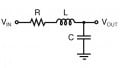
A first-order RC high-pass circuit is implemented as follows:
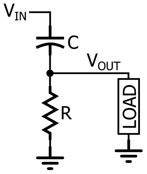
$$\frac{V_{OUT}}{V_{IN}}=\frac{R}{\frac{1}{sC}+R}=\frac{sRC}{1+sRC}=\frac{s}{s+\frac{1}{RC}}$$
The input-to-output behavior of a first-order high-pass filter can be described by the following standardized transfer function:
$$T(s)_{HP}=\frac{a_{1}s}{s+\omega _{O}}$$
Let’s compare this to the corresponding low-pass expression:
$$T(s)_{LP}=\frac{a_{O}}{s+\omega _{O}}$$
As you can see, the denominators are the same. In both cases, we have a pole at s = –ωO, meaning that both the low-pass filter and the high-pass filter will have the following characteristics:
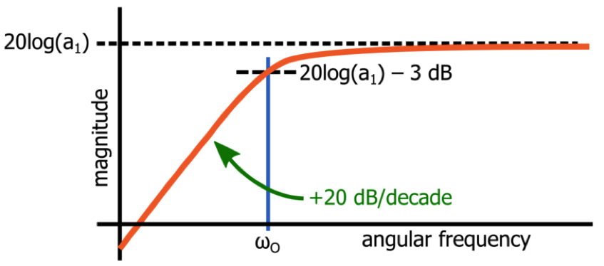
- The magnitude response at ωO will be 3 dB below the maximum magnitude response; with a passive filter, the maximum magnitude response is unity, in which case the value at ωO is –3 dB.
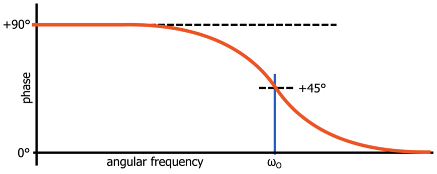
- The absolute value of the circuit’s phase shift at ωO will be 45°.
Thus, the response at ωO in these two circuits is very similar. However, the response at frequencies above and below ωO is influenced by the numerator of T(s), and the difference between the two numerators is what makes a low-pass filter very different from a high-pass filter.
The Effect of the Numerator
The numerator of T(s)HP tells us two things: the initial slope of the magnitude response will be +20 dB/decade, and the maximum magnitude will be a1. Let’s take a closer look at these two characteristics.
Initial Slope
Since we now have the variable s in the numerator, we will have a transfer-function zero at whatever value of s causes the numerator to equal zero. In the case of a first-order high-pass filter, the entire numerator is multiplied by s, so the zero is at s = 0.
How does a zero at s = 0 affect the magnitude and phase response of an actual circuit? First, let’s consider the magnitude. We know that a zero will cause the slope of the Bode plot curve to increase by 20 dB/decade. However, this increase occurs at ω = 0 rad/s (or ƒ = 0 Hz), and here’s the catch: the horizontal axis of the Bode plot never reaches 0 Hz. It’s a logarithmic axis, which means that the frequency decreases from 10 Hz to 1 Hz, to 0.1 Hz, to 0.01 Hz, and so forth. It never gets to 0 Hz. Consequently, we never see the corner frequency of the zero at ω = 0 rad/s.
Instead, the magnitude curve simply begins with a slope of +20 dB/decade. The magnitude continues to increase up to the pole frequency; the pole reduces the slope by 20 dB/decade, resulting in a response that becomes flat (i.e., slope = 0 dB/decade) and remains flat as ω increases toward infinity.
Maximum Gain
All we need is a bit of mathematical manipulation to see that the maximum gain of a high-pass filter will be equal to a1. From the general shape of the high-pass filter magnitude response, we know that the gain cannot decrease as ω increases toward infinity. Thus, we can find the maximum gain by evaluating T(s) for s → ∞. In the denominator, we have s + ωO. Something added to infinity is infinity, so in this case, we can simplify T(s) as follows:
$$T(s→∞)=\frac{a_{1}s}{s}$$
The s in the numerator and the s in the denominator cancel out, such that
$$T(s→∞)=a_{1}$$
High-Pass Filter Phase Response
As mentioned above, a zero contributes +90° of phase shift to a system’s phase response, with +45° of phase shift at the zero frequency. The phase shift reaches +90° at a frequency that is one decade above the zero frequency, but a high-pass filter has a zero at ω = 0 rad/s, and you can’t specify a frequency that is one decade above 0 rad/s—again, we’re dealing with a logarithmic scale here, which means that the horizontal axis will never reach 0 rad/s, nor will it ever reach a frequency that is one decade above 0 rad/s (such a frequency doesn’t really exist: 0 rad/s × 10 = 0 rad/s).
The result of all this is that the high-pass filter phase response has an initial value of +90°. In other words, all low-frequency input signals will be shifted by +90°, and then the phase shift will begin to decrease as the input frequency approaches the pole frequency:
Conclusion
We’ve examined the standard transfer function for a first-order high-pass filter, and we’ve seen how this transfer function leads to the characteristics of the high-pass magnitude and phase response.
In the next article, we’ll see that the low-pass transfer function and the high-pass transfer function can be combined into a general first-order transfer function, and we’ll also briefly consider the first-order all-pass filter.