Facebook
 Google
 GitHub
 Linkedin
Changing the Current Mirror Input-Output Ratio
Current mirrors need not be restricted to a 1:1 relationship between the input and output currents. If the critical transistor on the output side is increased in size, its collector current is increased as well.
In a bipolar transistor, the current ratio is determined by the size of the emitter (more precisely, the active emitter length). In practice, however, an accurate ratio is only achieved if you work with a number of identical emitters.
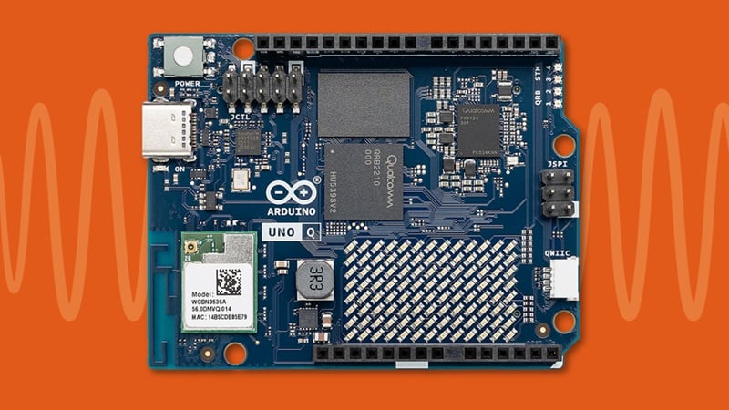
In Figure 4-15, for example, Q1 has one emitter while Q2 has three (they can all be in the same base). This results in an output current (I2) that is three times that of the primary current (I1).
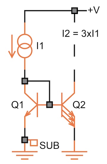
Figure 4-15. A simple current mirror with a 1:3 current ratio.
In Figure 4-16, Q1 has three emitters, and Q1 has one, causing I2 to have one-third the value of I1. Any ratio is possible (such as 3:2 or 5:3).
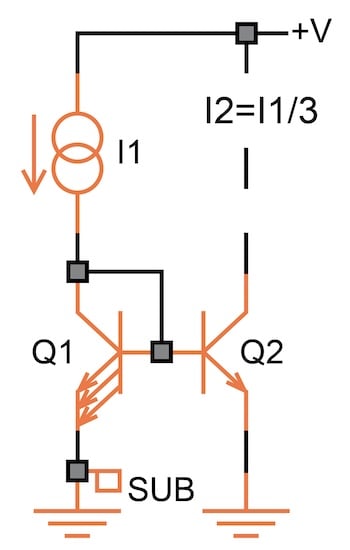
Figure 4-16. A simple current mirror with a 3:1 current ratio.
In a CMOS design, the ratio can be obtained simply by varying the channel width of one of the transistors, but the best matching is achieved by using multiple identical devices. In Figure 4-17, the multiple devices are signified using the “M=3” device multiplication parameter for transistor M2.
Figure 4-17. A MOS current mirror with a 1:3 current ratio.
This scheme can be expanded to create multiple currents (i.e., additional transistors with their bases and emitters connected in parallel to those of Q2, but their collectors separate) in any ratio you desire.
In bipolar circuits, however, there’s a limit: the base current for each additional emitter is supplied by I1. Thus, if Q2 has three emitters (or two additional transistors), the systematic error is 4% for transistors with a minimum gain of 100. With nine additional emitters, this increases to 10%.
Adding an Extra Transistor to Supply the Base Currents
There’s a solution to this (you may have noticed that there’s always a solution—it just takes one, or a few, additional transistors). As shown in Figure 4-18, with the help of Q3, the base current for Q1 and Q2 is supplied not from I1 but from the positive supply. The base current error is therefore divided by the gain of Q3. In this way, you can not only create large current ratios but also drive a substantial number of separate transistors.
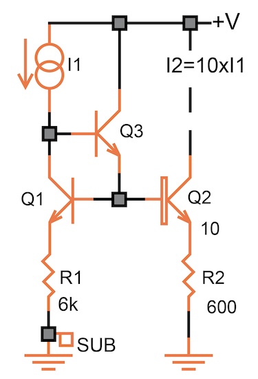
Figure 4-18. Adding an additional transistor, Q3, to supply the base currents.
In Figure 4-18, emitter resistors are also used to get less of a change in I2 with a varying output voltage (0.7% from 0.7 V to 5 V). If you have 10 separate transistors, they all get 6 kΩ in the emitter. If the current is simply multiplied by 10, R2 has one-tenth the value of R1.
Remember that the best matching is achieved if the resistors consist of identical sections. For example, you’d create a 600 Ω unit resistor and use one resistor for Q2 and 10 unit resistors in series for Q1.
If you’re thinking of turning I1 on and off rapidly, be aware that this circuit is very slow to turn off—there’s no discharge path for the bases of Q1 and Q2. A resistor (or another current sink) from these bases to ground helps to speed up the turn-off time.