Facebook
 Google
 GitHub
 Linkedin
Component Failure Analysis (Continued)
“I consider that I understand an equation when I can predict the properties of its solutions, without actually solving it.” —P.A.M Dirac, physicist
There is a lot of truth to that quote from Dirac. With a little modification, I can extend his wisdom to electric circuits by saying, “I consider that I understand a circuit when I can predict the approximate effects of various changes made to it without actually performing any calculations.”
At the end of the series and parallel circuits chapter, we briefly considered how circuits could be analyzed in a qualitative rather than quantitative manner. Building this skill is an important step towards becoming a proficient troubleshooter of electric circuits. Once you have a thorough understanding of how any particular failure will affect a circuit (i.e. you don’t have to perform any arithmetic to predict the results), it will be much easier to work the other way around: pinpointing the source of trouble by assessing how a circuit is behaving.
Also shown at the end of the series and parallel circuits chapter was how the table method works just as well for aiding failure analysis as it does for the analysis of healthy circuits. We may take this technique one step further and adapt it for total qualitative analysis. By “qualitative” I mean working with symbols representing “increase,” “decrease,” and “same” instead of precise numerical figures.
We can still use the principles of series and parallel circuits, and the concepts of Ohm’s Law. We’ll just use symbolic qualities instead of numerical quantities. By doing this, we can gain more of an intuitive “feel” for how circuits work rather than leaning on abstract equations, attaining Dirac’s definition of “understanding.”
Component Failure Analysis on Complex Circuits
Enough talk. Let’s try this technique on a real circuit example and see how it works:
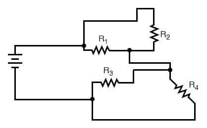
This is the first “convoluted” circuit we straightened out for analysis in the last section. Since you already know how this particular circuit reduces to series and parallel sections, I’ll skip the process and go straight to the final form:
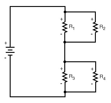
R3 and R4 are in parallel with each other; so are R1 and R2. The parallel equivalents of R3//R4 and R1//R2 are in series with each other. Expressed in symbolic form, the total resistance for this circuit is as follows:
RTotal = (R1//R2)—(R3//R4)
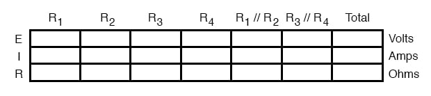
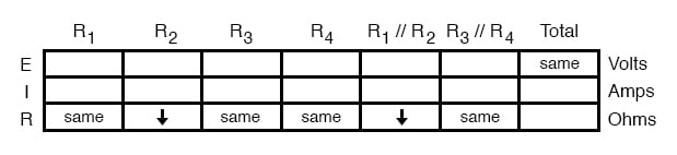
First, we need to formulate a table with all the necessary rows and columns for this circuit:
Analysis on Failure Scenario
Next, we need a failure scenario. Let’s suppose that resistor R2 were to fail shorted. We will assume that all other components maintain their original values. Because we’ll be analyzing this circuit qualitatively rather than quantitatively, we won’t be inserting any real numbers into the table.
For any quantity unchanged after the component failure, we’ll use the word “same” to represent “no change from before.” For any quantity that has changed as a result of the failure, we’ll use a down arrow for “decrease” and an up arrow for “increase.”
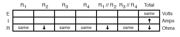
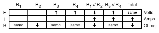
As usual, we start by filling in the spaces of the table for individual resistances and total voltage, our “given” values:
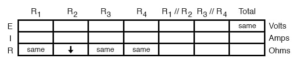
The only “given” value different from the normal state of the circuit is R2, which we said was failed shorted (abnormally low resistance). All other initial values are the same as they were before, as represented by the “same” entries. All we have to do now is work through the familiar Ohm’s Law and series-parallel principles to determine what will happen to all the other circuit values.
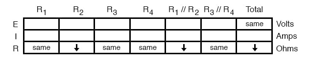
First, we need to determine what happens to the resistances of parallel subsections R1//R2 and R3//R4. If neither R3 nor R4 have changed in resistance value, then neither will their parallel combination.
However, since the resistance of R2 has decreased while R1 has stayed the same, their parallel combination must decrease in resistance as well:
Now, we need to figure out what happens to the total resistance. This part is easy: when we’re dealing with only one component change in the circuit, the change in total resistance will be in the same direction as the change of the failed component. This is not to say that the magnitude of change between individual component and total circuit will be the same, merely the direction of change. In other words, if any single resistor decreases in value, then the total circuit resistance must also decrease, and vice versa.
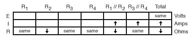
In this case, since R2 is the only failed component, and its resistance has decreased, the total resistance must decrease:
Now we can apply Ohm’s Law (qualitatively) to the Total column in the table. Given the fact that total voltage has remained the same and total resistance has decreased, we can conclude that total current must increase (I=E/R).
Using Qualitative Assessment of Ohm’s Law in Failure Analysis
In case you’re not familiar with the qualitative assessment of an equation, it works like this. First, we write the equation as solved for the unknown quantity. In this case, we’re trying to solve for current, given voltage and resistance:

Now that our equation is in the proper form, we assess what change (if any) will be experienced by “I,” given the change(s) to “E” and “R”:
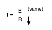
If the denominator of a fraction decreases in value while the numerator stays the same, then the overall value of the fraction must increase:
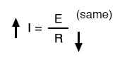
Therefore, Ohm’s Law (I=E/R) tells us that the current (I) will increase. We’ll mark this conclusion in our table with an “up” arrow:
With all resistance places filled in the table and all quantities determined in the Total column, we can proceed to determine the other voltages and currents. Knowing that the total resistance in this table was the result of R1//R2 and R3//R4 in series, we know that the value of total current will be the same as that in R1//R2 and R3//R4 (because series components share the same current).
Therefore, if total current increased, then current through R1//R2 and R3//R4 must also have increased with the failure of R2:
Fundamentally, what we’re doing here with a qualitative usage of Ohm’s Law and the rules of series and parallel circuits is no different from what we’ve done before with numerical figures. In fact, it’s a lot easier because you don’t have to worry about making an arithmetic or calculator keystroke error in a calculation. Instead, you’re just focusing on the principles behind the equations.
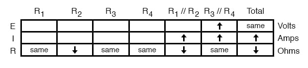
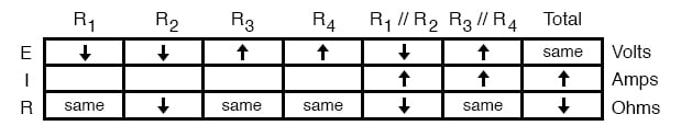
From our table above, we can see that Ohm’s Law should be applicable to the R1//R2 and R3//R4 columns. For R3//R4, we figure what happens to the voltage, given an increase in current and no change in resistance. Intuitively, we can see that this must result in an increase in voltage across the parallel combination of R3//R4:
Using the Circuit Analysis Rules on Failure Analysis
But how do we apply the same Ohm’s Law formula (E=IR) to the R1//R2 column, where we have resistance decreasing and current increasing? It’s easy to determine if only one variable is changing, as it was with R3//R4, but with two variables moving around and no definite numbers to work with, Ohm’s Law isn’t going to be much help.
However, there is another rule we can apply horizontally to determine what happens to the voltage across R1//R2: the rule for voltage in series circuits. If the voltages across R1//R2 and R3//R4 add up to equal the total (battery) voltage and we know that the R3//R4 voltage has increased while total voltage has stayed the same, then the voltage across R1//R2 must have decreased with the change of R2‘s resistance value:
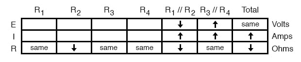
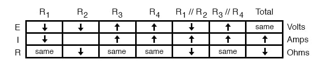
Now we’re ready to proceed to some new columns in the table. Knowing that R3 and R4 comprise the parallel subsection R3//R4, and knowing that voltage is shared equally between parallel components, the increase in voltage seen across the parallel combination R3//R4 must also be seen across R3 and R4 individually:
The same goes for R1 and R2. The voltage decrease seen across the parallel combination of R1 and R2 will be seen across R1 and R2 individually:
Applying Ohm’s Law vertically to those columns with unchanged (“same”) resistance values, we can tell what the current will do through those components. Increased voltage across an unchanged resistance leads to increased current. Conversely, decreased voltage across an unchanged resistance leads to decreased current:
Once again we find ourselves in a position where Ohm’s Law can’t help us: for R2, both voltage and resistance have decreased, but without knowing how much each one has changed, we can’t use the I=E/R formula to qualitatively determine the resulting change in current. However, we can still apply the rules of series and parallel circuits horizontally. We know that the current through the R1//R2 parallel combination has increased, and we also know that the current through R1 has decreased.
One of the rules of parallel circuits is that total current is equal to the sum of the individual branch currents. In this case, the current through R1//R2 is equal to the current through R1 added to the current through R2. If current through R1//R2 has increased while current through R1 has decreased, current through R2 must have increased:
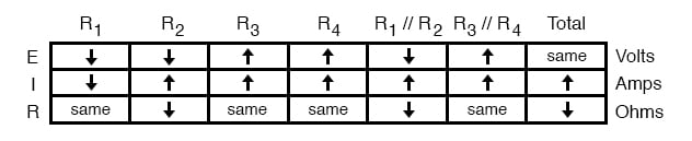
And with that, our table of qualitative values stands completed. This particular exercise may look laborious due to all the detailed commentary, but the actual process can be performed very quickly with some practice. An important thing to realize here is that the general procedure is little different from quantitative analysis: start with the known values, then proceed to determining total resistance, then total current, then transfer figures of voltage and current as allowed by the rules of series and parallel circuits to the appropriate columns.
A few general rules can be memorized to assist and/or to check your progress when proceeding with such an analysis:
- For any single component failure (open or shorted), the total resistance will always change in the same direction (either increase or decrease) as the resistance change of the failed component.
- When a component fails shorted, its resistance always decreases. Also, the current through it will increase, and the voltage across it may drop. I say “may” because in some cases it will remain the same (case in point: a simple parallel circuit with an ideal power source).
- When a component fails open, its resistance always increases. The current through that component will decrease to zero, because it is an incomplete electrical path (no continuity). This may result in an increase of voltage across it. The same exception stated above applies here as well: in a simple parallel circuit with an ideal voltage source, the voltage across an open-failed component will remain unchanged.
RELATED WORKSHEETS: