 Facebook
 Google
 GitHub
 Linkedin
Understanding Spread-Spectrum RF Communication
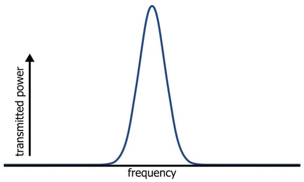
Throughout this book, we have visualized RF signals as both waveforms in the time-domain and distinct shapes in the frequency domain. These shapes are often rather tall and narrow, indicating that a large amount of transmitted energy is concentrated in a relatively small range of frequencies:
It turns out that we can also produce a very different kind of spectrum, namely, one that is wider and shorter. In other words, we can change an RF circuit such that it generates a signal whose transmitted power is spread out over a wider range of frequencies. These signals are appropriately described as “spread spectrum”:
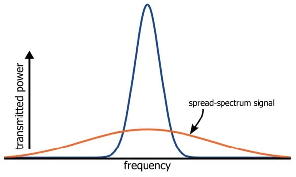
It’s important to understand that the total transmitted power is not reduced. What changes is the peak power, because the transmitted power is distributed over a wider frequency band.
How to Spread a Spectrum
Changing a standard RF signal to a spread-spectrum signal is a process of exchanging peak power for bandwidth. However, we don’t need to take any specific action to decrease the peak power: If everything else in the circuit remains the same, the overall transmitted power will also remain the same. All we need to do is increase the bandwidth of the signal, and the natural result will be the distribution of the available RF energy into a wider, shorter spectrum like the one shown above.
We know from previous pages that the bandwidth of an RF waveform corresponds to the highest frequencies present in the baseband signal. In the amplitude modulation page, we saw how the positive and negative frequencies of the baseband spectrum are shifted upward to form a symmetrical spectrum centered on the carrier frequency. Thus, if we use higher frequencies in the baseband signal, the bandwidth of the modulated signal will increase. We can spread a spectrum, then, by incorporating higher frequencies into the baseband signal. But how do we accomplish this without changing the baseband information?
The solution is something called a spreading sequence, also known as a pseudo-noise (PN) code or a pseudo-random-noise (PRN) code. This is a digital sequence that is intended to resemble a random succession of ones and zeros. The baseband signal is multiplied by the spreading sequence, except that a logic zero is treated like a negative one, such that the waveform is unchanged during the logic-high periods and inverted during the logic-low periods. The following diagram demonstrates this process:
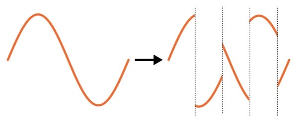
As you can see, the frequency of the PN code (referred to as the “chip rate,” because each pulse is called a “chip”) is higher than the frequency of the baseband signal. We can intuitively recognize that chopping up the baseband signal in this way will introduce higher-frequency energy, and actually the factor by which the spectrum is spread is equal to the ratio of the chip rate to the baseband data rate.
How to De-Spread a Spectrum
We have now increased the bandwidth of the baseband signal and, consequently, that of the transmitted signal, but the information appears to be seriously altered. How do we recover the data that was originally encoded in the baseband waveform? Actually, it’s quite simple (at least in theory): all we need to do is multiply the received waveform by the same PN code. The sections that the transmitter multiplied by one will be multiplied by one again (i.e., they remain unchanged), and the sections that were inverted will be inverted again (i.e., returned to their original state).
Why Spread a Spectrum?
The procedure described thus far may seem like unnecessary complexity, but in certain situations it is well worth the effort. The fundamental benefit might be aptly described as “selectivity”: spread-spectrum communication gives the receiver a greater ability to select the desired signal from among the various other signals that might be present in the relevant frequency band.
This selectivity results from an interesting effect of multiplying the received signals by the PN code: This receiver multiplication will de-spread only the desired signal, or more specifically, only the signal that was originally multiplied by the same PN code. If the unwanted signal has a narrowband (i.e., non-spread) spectrum, the PN code will spread it. If the unwanted signal has a spread spectrum that was created with a different PN code, the inverted and non-inverted sections will not align with the ones and zeros, and thus it will not be restored to its original state.
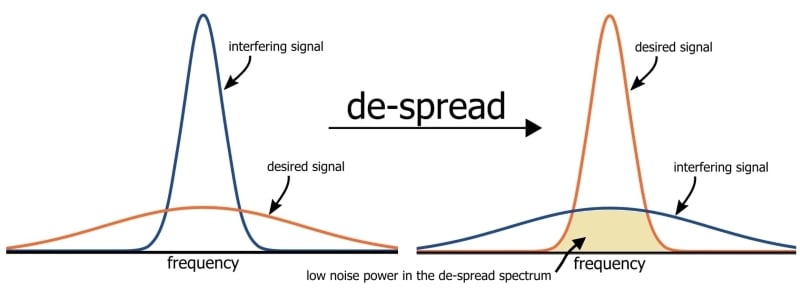
Let’s consider first how spreading the spectrum makes a system resistant to jamming and interference. If a strong interfering signal is transmitted at a frequency close to the center frequency of a non-spread spectrum, it will be difficult for the receiver to separate the interference from the desired signal. But if the spectrum is spread before transmission, the de-spreading operation will spread the interfering spectrum and restore the desired spectrum, resulting in a reduced level of interference:
The same concept applies to wireless systems in which multiple devices must share a limited range of available frequencies. Such systems can employ various methods of minimizing problems associated with interference, and spread-spectrum communication is one of them. Different devices can share the same band and their spectra can overlap; the receiver selects the desired signal by means of the PN code, which will de-spread only the desired signal.
Frequency Hopping
The spread-spectrum technique that we have discussed so far is called direct-sequence spread spectrum (DSSS). An alternative approach is to maintain the narrowband nature of the transmitted signals but to periodically change the carrier frequency. This is called frequency hopping, and it achieves a similar reduction in peak power if the transmissions are averaged over time. Like DSSS, it offers improved resistance to interference because an interfering signal will no longer corrupt the desired signal after the communicating devices have switched to a new carrier frequency.
Summary
- A spread-spectrum signal can be created by multiplying the existing baseband signal by a spreading sequence, also known as a PN code.
- The original signal is recovered by multiplying the spread-spectrum signal by the same PN code.
- A spread-spectrum signal has lower peak power, equal total power, and wider bandwidth. In other words, the available transmission power is distributed over a wider range of frequencies.
- Spread-spectrum techniques make a system more robust against jamming and interference.
- Similar results can be obtained by periodically changing the signal’s carrier frequency; this approach is called frequency hopping.


so there are only 6 chapters?