 Facebook
 Google
 GitHub
 Linkedin
L-Match Impedance Matching Circuits
This calculator is designed to compute for the parameters needed to design a L-Match Impedance Circuit
Outputs
Overview
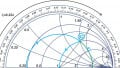
The L-match impedance matching circuit is one of the circuits used to match the impedance between two points, usually a source and a load. The circuit got its name because the inductor and the capacitor form an L-shape (see schematic below). Note that the inductor and capacitor can be interchanged depending on the input. If you need to block direct current, then the capacitor is placed near the source. Otherwise, the inductor is placed near the source, as seen in the schematic below.
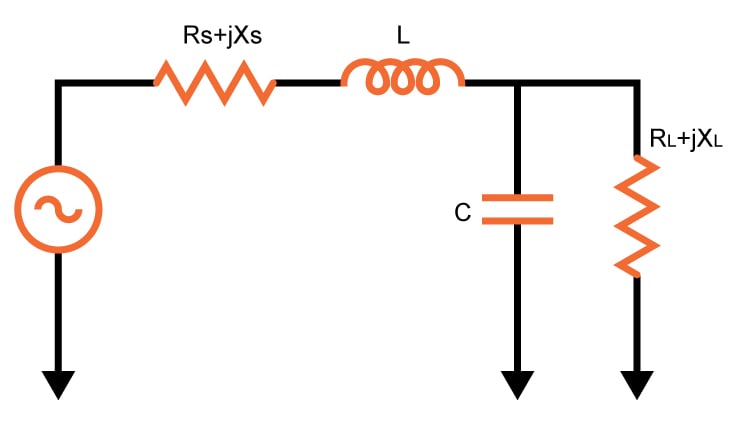
This calculator will help you determine the correct values for the inductor and capacitor in an L-match impedance matching circuit. The required parameters are the signal (or source) frequency, the impedance of the source and the impedance of the load. You can also specify if the circuit will pass direct current or block it. The inductor quality factor is also computed.
Equations
For Pass DC Current:
$$Z_{input}=\left [ \left \{ R_{L}+jX_{L}+\left ( \frac{1}{j\cdot \omega\cdot C} \right )\right \}//\left ( j\omega\cdot L \right ) \right]$$
For Block DC Current:
$$Z_{input}=\left \{\left [R_{L}+jX_{L}+ ( j\omega\cdot L ) \right ]// \left ( \frac{1}{j\cdot \omega\cdot C } \right ) \right \}$$
Applications
Impedance matching is important in electrical engineering because it allows for maximum power transfer between two points. In telephone systems, for example, minimizing echo on long-distance lines is achieved using match impedances. The telephone hybrid coil, where two wires are converted into four wires can also be achieved via matching.
In audio amplifiers, impedances are not matched as it is typical for amplifiers to have output impedances that are lower than the load impedance for better speaker damping. But for higher-power amplifiers, such as those that use vacuum tubes, impedance-changing circuits are used to get a low output impedance in order to better match the amplifier's performance to the load impedance.
Further Reading
Related Content


Threre is a gross conceptual error in the accompanying text to this calculator.
In the last phrase of the second paragraph of Overview it is stated “The inductor quality factor is also computed. “
This is erroneous. What is computed is an auxiliary quantity to solve for the values of the matching reactances. In textbooks this value can be called “circuit Q” but never would it be the inductor (“coil”) Q, which see, this calculator, in fact the formulae employed to compute, requires for accuracy the Q of the inductor be at least 20 times the circuit Q in order to keep the insertion losses low, and the impedance transformation within engineering tolerances.
I suggest you rephrase the last phrase to the more accurate “circuit” Q, include in the formulas below Q= (Rhi/Rlo -1)^(1/2); which stems from the impedance transformation.
On the other hand this calculator would be more useful if a more complex calculation was done to include components imperfections (capacitor d dissipation and inductor Q factors) and compute as well the insertion loss of these structures.
The load impedance and matching network capacitor are in parallel. I couldn’t understand how they are just summed up.