 Facebook
 Google
 GitHub
 Linkedin
T-Match Impedance Matching Circuits
A tool designed to compute the values to be used in a T-match Impedance Circuit
Outputs
Overview
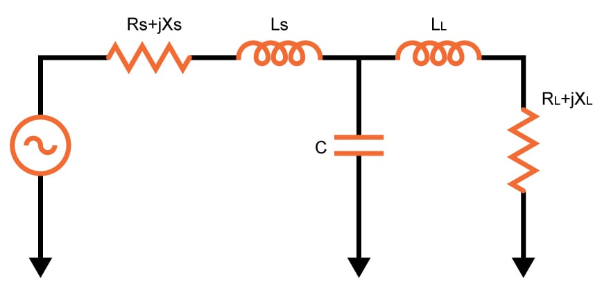
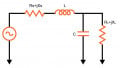
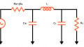
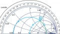
The T-match impedance matching circuit is one of the circuits used to match the impedance between two points, usually a source and a load. The circuit got its name because the inductor and the capacitor form a T-shape as shown in the schematic diagram below. You can either pass or block DC current depending on the placement of the inductors and capacitors. The circuit below is a pass dc current circuit. Interchange the inductors and the capacitor and you have a block DC current circuit.
Equations
For Pass DC Current:
$$Z_{input}=\left [ \left ( R_{L}+jX_{L}+j\omega\cdot L_{L} \right )//\left (\frac{1}{j\cdot \omega\cdot C} \right ) \right ]+j\omega\cdot L_{s}$$
For Block DC Current:
$$Z_{input}=\left \{ \left [ R_{L}+jX_{L}+\left ( \frac{1}{j\cdot \omega\cdot C_{L}} \right )\right ]//\left ( j\omega\cdot L \right ) \right \}+\left ( \frac{1}{j\cdot \omega\cdot C_{S}} \right )$$
Applications
Impedance matching is important in electrical engineering because it allows for maximum power transfer between two points. In telephone systems, for example, minimizing echo on long-distance lines is achieved using match impedances. The telephone hybrid coil, where two wires are converted into four wires can also be achieved via matching.
In audio amplifiers, impedances are not matched as it is typical for amplifiers to have output impedances that are lower than the load impedance for better speaker damping. But for higher-power amplifiers, such as those that use vacuum tubes, impedance-changing circuits are used to get a low output impedance in order to better match the amplifier's performance to the load impedance.
Further Reading
Related Content


usefull tool
This is the perfect tool for me. This is very useful.
foundation repair in chicago, il
Thanks for sharing such a great tool. Concrete driveway fort worth