Facebook
 Google
 GitHub
 Linkedin
The Bipolar Junction Transistor (BJT) as a Switch
Transistors are active devices that can perform both switching and amplification. These two operations are not fundamentally different—in both cases, a relatively large current flowing through the device is regulated by a small-amplitude or low-power signal applied to the input terminal.
However, the terms “switch” and “amplifier” help us to concisely convey differences deriving from the way in which a transistor is used and from the objective of the circuit designer. In this tutorial, we will focus on switching, and in the next tutorial, we will examine a BJT small-signal amplifier.
The Purpose of a Switch
Electronic systems are often responsible for controlling motors, solenoids, heaters, and other types of high-power equipment. The thing being controlled is called the load, and by “controlled” we mean simply turned on and turned off—the purpose of the electronics is to supply power to the load and remove power from the load in accordance with commands generated by, for example, a comparator circuit, a collection of interconnected logic gates, or a human operator.
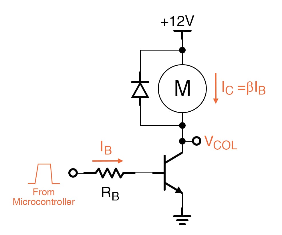
Nowadays, the commands that control an electronic switch will frequently come from a microcontroller. For example, an electromechanical system might consist of several DC motors that need to be individually started and stopped in a precise sequence that changes according to environmental conditions.
The instructions executed by a microcontroller monitor sensors, implement the required sequence, and generate digital signals intended for each motor; a logic-high signal indicates that the motor should be rotating, and a logic-low signal indicates that the motor should be stopped. Logic-low signals will be very close to 0 V, and a common logic-high level is 3.3 V.
We can’t use the microcontroller to directly control the motors, because the signals generated by microprocessors and other types of digital ICs cannot supply the large amounts of current required to drive high-power loads.
Discrete transistors, on the other hand, can supply large amounts of current. Thus, if we insert BJT switches between the microcontroller and the motors, we have an effective method of controlling high-power loads by means of low-power digital signals.
Cutoff and Saturation
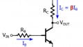
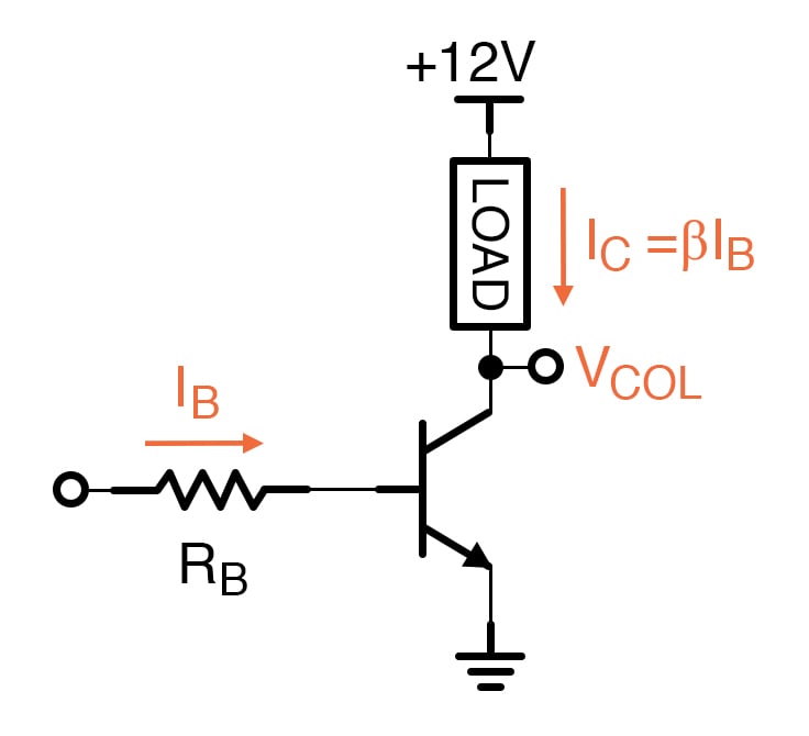
When we use a BJT as a basic “low-side” switch, the goal is to turn the load off by preventing current flow and to turn the load on by allowing current to flow freely from the supply voltage, through the load, through the BJT’s collector and emitter, to ground. Preventing current is easy enough: a logic-low control signal will not forward-bias the BE junction, and thus the transistor will be in cutoff.
But how do we cause current to flow freely through the load? Do we want an on-state transistor switch to operate in forward active mode or saturation mode? As we’ll see in the next tutorial, forward active mode provides high gain, meaning that very small changes in input voltage can create large and proportional changes in output current.
In a switching circuit, the goal is not to provide proportional changes in output current; rather, we simply want to drive the transistor into full conduction. Thus, a BJT switch transitions between cutoff mode and saturation mode. We don’t limit the input voltage or the input current in an attempt to keep the transistor in forward active mode.
Maximum Current
The following plot, which is the same as a plot that we saw in the previous tutorial except that the labels have been changed, helps us to understand why saturation mode provides maximum current to a switched load.
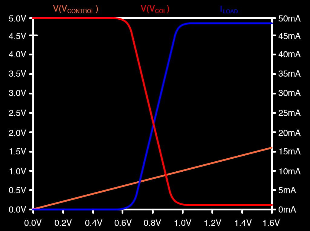
The collector voltage (VCOL) decreases during forward active operation and levels off when the transistor enters saturation. We approximate the saturation-mode collector voltage as a constant VCE(sat) = 0.2 V, and we think of VCE(sat) as the lowest collector voltage that is possible during normal operation.
If we imagine that the load is a resistance placed between the supply voltage and the collector voltage, the current through the load will be greatest when the voltage across the load is maximized, and since the supply voltage is fixed, voltage across the load is maximized when the collector voltage reaches VCE(sat).
Conclusion
This tutorial gave a basic example of a transistor-based switch circuit and explained why we utilize cutoff and saturation modes when performing BJT switching. In the next tutorial, we will explore BJT amplification using a simple circuit that increases the amplitude of a sinusoidal input signal.
Related Content