Facebook
 Google
 GitHub
 Linkedin
DC Electric Circuits
DC Bridge Circuits
19 questions By Tony R. Kuphaldt
-
Question 13 of 19
A strain gauge is a device used to measure the strain (compression or expansion) of a solid object by producing a resistance change proportional to the amount of strain:
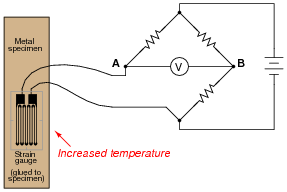
The bridge circuit is supposed to respond to changes in specimen strain, but explain what will happen to the voltage measured across this bridge circuit (VAB) if the specimen’s temperature increases (with no stress applied), assuming that the bridge begins in a balanced condition with no strain on the gauge, at room temperature. Assume a positive α value for the strain gauge conductors.
What does this indicate about the effectiveness of this device as a strain-measuring instrument?
Reveal answerIf the specimen heats up, a voltage will develop between points A and B, with A being positive and B being negative.
Notes:Be sure to have your students explain how they arrived at their answers for polarity across the voltmeter terminals.
Ask your students whether or not the fact of the circuit’s sensitivity to temperature invalidates its use as a strain-measuring system. Is it impossible to obtain a reliable measurement of strain, if we know temperature also affects the circuit output voltage? How could we compensate for the effects of temperature on the system?
-
Question 14 of 19
Predict how the operation of this thermistor bridge circuit will be affected as a result of the following faults. Consider each fault independently (i.e. one at a time, no multiple faults):

- Thermistor R1 fails open:
- Thermistor R3 fails open:
- Solder bridge (short) across thermistor R3:
- Resistor R2 fails open:
- Resistor R4 fails open:
For each of these conditions, explain why the resulting effects will occur.
Reveal answer- Thermistor R1 fails open: Voltmeter “pegs” in the negative direction.
- Thermistor R3 fails open: Voltmeter “pegs” in the positive direction.
- Solder bridge (short) across thermistor R3: Voltmeter “pegs” in the negative direction.
- Resistor R2 fails open: Voltmeter “pegs” in the positive direction.
- Resistor R4 fails open: Voltmeter “pegs” in the negative direction.
Notes:The purpose of this question is to approach the domain of circuit troubleshooting from a perspective of knowing what the fault is, rather than only knowing what the symptoms are. Although this is not necessarily a realistic perspective, it helps students build the foundational knowledge necessary to diagnose a faulted circuit from empirical data. Questions such as this should be followed (eventually) by other questions asking students to identify likely faults based on measurements.
-
Question 15 of 19
Predict how the voltage polarity between test points A and B will be affected as a result of the following faults. Consider each fault independently (i.e. one at a time, no multiple faults):
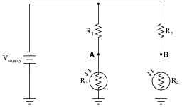
- Photoresistor R4 fails open:
- Photoresistor R3 fails open:
- Solder bridge (short) across photoresistor R4:
- Resistor R2 fails open:
- Resistor R1 fails open:
For each of these conditions, explain why the resulting effects will occur.
Reveal answer- Photoresistor R4 fails open: Test point B will be positive with respect to test point A (negative).
- Photoresistor R3 fails open: Test point A will be positive with respect to test point B (negative).
- Solder bridge (short) across photoresistor R4: Test point A will be positive with respect to test point B (negative).
- Resistor R2 fails open: Test point A will be positive with respect to test point B (negative).
- Resistor R1 fails open: Test point B will be positive with respect to test point A (negative).
Notes:The purpose of this question is to approach the domain of circuit troubleshooting from a perspective of knowing what the fault is, rather than only knowing what the symptoms are. Although this is not necessarily a realistic perspective, it helps students build the foundational knowledge necessary to diagnose a faulted circuit from empirical data. Questions such as this should be followed (eventually) by other questions asking students to identify likely faults based on measurements.