Facebook
 Google
 GitHub
 Linkedin
DC Electric Circuits
DC Bridge Circuits
19 questions By Tony R. Kuphaldt
-
Question 16 of 19
This bridge circuit is suppose to generate an output voltage proportional to the difference between light exposure on the two photocells:

However something has failed in this circuit, because the voltmeter is “pegged” fully negative and will not change with varying light exposures on the two cells. Identify at least two possible failures that could cause the voltmeter to over-range in the negative direction.
Reveal answerHere are two failures, although they are not the only possibilities:
- R1 could have failed shorted.
- Photocell R3 could have failed open.
Notes:Be sure to ask your students to describe failures other than the two mentioned in the answer. And, for all answers given, be sure to ask students how they determined those faults would cause the observed “negative pegging” of the voltmeter. As usual, the method of solution is much more important than the actual answer in this question.
-
Question 17 of 19
Explain how this strain gauge circuit exploits a property of bridge circuits to provide automatic temperature compensation (so that changes in specimen temperature do not compromise strain measurement accuracy):
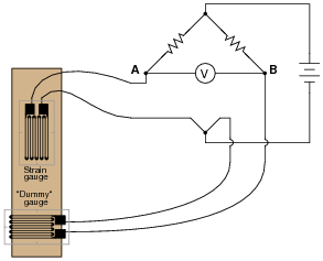
Reveal answerThe “dummy” gauge is attached to the specimen in such a way that it is not subjected to strain like the “working” gauge is. It it merely exposed to the same specimen temperature. The action of this circuit is easiest to comprehend in a scenario where there is no stress applied to the specimen, but its temperature changes.
Follow-up question: suppose the “dummy” strain gauge develops an open failure, so no current may pass through it. Identify the polarity of the voltage drop that will develop across the voltmeter as a result of this fault.
Notes:Because bridge circuits are inherently differential circuits, it is possible to perform neat “tricks” such as this where the effects of the undesired influence (temperature) become canceled. Incidentally, the principle of cancellation by differential measurement is one that is very common in electronic systems, especially instrumentation systems.
-
Question 18 of 19
The following bridge circuit uses two strain gauges (one to measure strain, the other to compensate for temperature changes), the amount of strain indicated by the voltmeter in the center of the bridge. Unfortunately, though, it has a problem. Instead of registering a very small voltage as it normally does, the voltmeter shows a large voltage difference, with point A positive and point B negative:
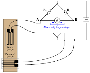
Something is wrong in the bridge circuit, because this voltage is present even when there is no physical stress on the specimen. Identify which of the following faults could cause the excessive voltage to appear across the voltmeter, and which could not. Consider only one of these faults at a time (no multiple, simultaneous faults):
- Resistor R1 failed open
- Resistor R1 failed shorted
- Resistor R2 failed open
- Resistor R2 failed shorted
- Strain gauge (measurement) failed open
- Strain gauge (measurement) failed shorted
- “Dummy” gauge (temperature compensation) failed open
- “Dummy” gauge (temperature compensation) failed shorted
- Voltage source is dead (no voltage output at all)
Reveal answer- Resistor R1 failed open Not possible
- Resistor R1 failed shorted Possible
- Resistor R2 failed open Possible
- Resistor R2 failed shorted Not possible
- Strain gauge (measurement) failed open Possible
- Strain gauge (measurement) failed shorted Not possible
- “Dummy” gauge (temperature compensation) failed open Not possible
- “Dummy” gauge (temperature compensation) failed shorted Possible
- Voltage source is dead (no voltage output at all) Not possible
Follow-up question: identify possible wire or connection failures in this circuit which could cause the same symptom to manifest.
Notes:This question helps students build the skill of eliminating unlikely fault possibilities, allowing them to concentrate instead on what is more likely. An important skill in system troubleshooting is the ability to formulate probabilities for various fault scenarios. Without this skill, you will waste a lot of time looking for unlikely faults, thereby wasting time.
For each fault scenario it is important to ask your students why they think it is possible or not possible. It might be that some students get the right answer(s) for the wrong reasons, so it is good to explore the reasoning for each answer.