Facebook
 Google
 GitHub
 Linkedin
DC Electric Circuits
DC Bridge Circuits
19 questions By Tony R. Kuphaldt
-
Question 10 of 19
Complete the wire connections necessary to make this a bridge circuit, where [(R1)/(R2)] = [(R3)/(R4)] at balance:
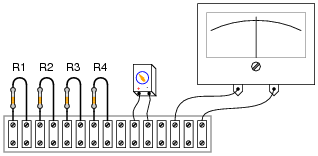
Reveal answerThis, of course, is not the only way to connect the components to make a bridge circuit!

Notes:Challenge your students to connect the resistors in a manner different from the diagram shown in the answer, to make a bridge circuit. A good way to do this is to project an image of the original components (with no interconnections drawn) on a whiteboard with a video projector, then have students use dry-erase markers to draw the connecting wires in place. If any errors are made, they can be very easily erased without erasing any components themselves.
-
Question 11 of 19
In the early days of electrical metrology, the best way to measure the value of an unknown resistance was to use a bridge circuit. Explain how a four-resistor bridge (a “Wheatstone” bridge) could be used to accurately measure an unknown resistance. What components would this bridge circuit have to be constructed from? Did the power source have to be precision as well? Did the voltmeter in the middle of the bridge have to be accurately calibrated?
Reveal answerSuch a bridge circuit needed to be built with three “standard” resistors, having precisely known resistances. At least one of these resistors needed to be adjustable, with a precision scale attached to it for indication of its resistance at any given position. The source (“excitation”) voltage did not not have to be precise, and the null meter only had to be sensitive and accurate at zero volts.
Notes:In the past I’ve lectured on Wheatstone bridges only to find a fair number of students completely misunderstanding the concept. The fact that a bridge circuit balances when the four arms’ resistances are in proportion is the easy part. What these students didn’t grasp is how such a bridge might be used to actually measure an unknown resistance, or why it was not possible for them to build a laboratory-usable Wheatstone bridge circuit with the cheap resistors found in their parts kits.
For example, when asked how such a bridge circuit might be used, it was not unusual to hear a student respond that they would make one of the arms of the bridge adjustable, then measure that arm of the bridge with their digital ohmmeter after having achieved balance in order to calculate the unknown resistance by ratio. Though it may seem humorous to an instructor that someone might not realize the sheer existence of a precise ohmmeter would render the bridge circuit obsolete, it nevertheless revealed to me how foreign the concept of a Wheatstone bridge as a resistance measuring circuit is to students working with modern test equipment. Such a technological “generation gap” is not to be underestimated!
In order for students to understand the practicality of a Wheatstone bridge, they need to realize that the only affordable calibration artifacts of the time were standard resistors and standard cells (mercury batteries).
-
Question 12 of 19
A strain gauge is a device used to measure the strain (compression or expansion) of a solid object by producing a resistance change proportional to the amount of strain. As the gauge is strained, its electrical resistance alters slightly due to changes in wire cross-section and length.
The following strain gauge is shown connected in a “quarter-bridge” circuit (meaning only one-quarter of the bridge actively senses strain, while the other three-quarters of the bridge are fixed in resistance):
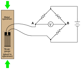
Explain what would happen to the voltage measured across this bridge circuit (VAB) if the strain gauge were to be compressed, assuming that the bridge begins in a balanced condition with no strain on the gauge.
Reveal answerThe bridge circuit will become more unbalanced, with more strain experienced by the strain gauge. I will not tell you what the voltmeter’s polarity will be, however!
Notes:Be sure to have your students explain how they arrived at their answers for polarity across the voltmeter terminals. This is the most important part of the question!