Suppose we wished to measure the resistance of some component located a significant distance away from our ohmmeter. Such a scenario would be problematic because an ohmmeter measures all resistance in the circuit loop, which includes the resistance of the wires (Rwire) connecting the ohmmeter to the component being measured (Rsubject):
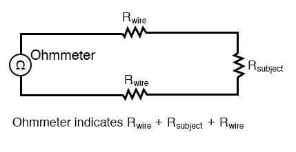
Usually, wire resistance is very small (only a few ohms per hundreds of feet, depending primarily on the gauge (size) of the wire), but if the connecting wires are very long, and/or the component to be measured has a very low resistance anyway, the measurement error introduced by wire resistance will be substantial.
An ingenious method of measuring the subject resistance in a situation like this involves the use of both an ammeter and a voltmeter. We know from Ohm’s Law that resistance is equal to voltage divided by current (R = E/I). Thus, we should be able to determine the resistance of the subject component if we measure the current going through it and the voltage dropped across it:
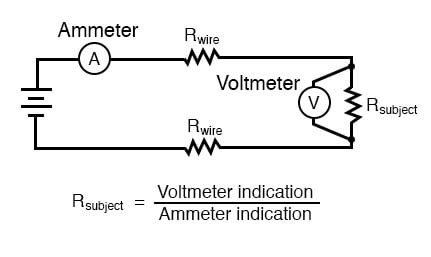
Current is the same at all points in the circuit, because it is a series loop. Because we’re only measuring voltage dropped across the subject resistance (and not the wires’ resistances), though, the calculated resistance is indicative of the subject component’s resistance (Rsubject) alone.
Our goal, though, was to measure this subject resistance from a distance, so our voltmeter must be located somewhere near the ammeter, connected across the subject resistance by another pair of wires containing resistance:
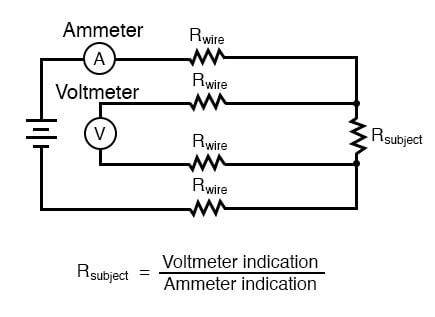
At first, it appears that we have lost any advantage of measuring resistance this way, because the voltmeter now has to measure voltage through a long pair of (resistive) wires, introducing stray resistance back into the measuring circuit again. However, upon closer inspection it is seen that nothing is lost at all, because the voltmeter’s wires carry miniscule current. Thus, those long lengths of wire connecting the voltmeter across the subject resistance will drop insignificant amounts of voltage, resulting in a voltmeter indication that is very nearly the same as if it were connected directly across the subject resistance:

Any voltage dropped across the main current-carrying wires will not be measured by the voltmeter, and so do not factor into the resistance calculation at all. Measurement accuracy may be improved even further if the voltmeter’s current is kept to a minimum, either by using a high-quality (low full-scale current) movement and/or a potentiometric (null-balance) system.
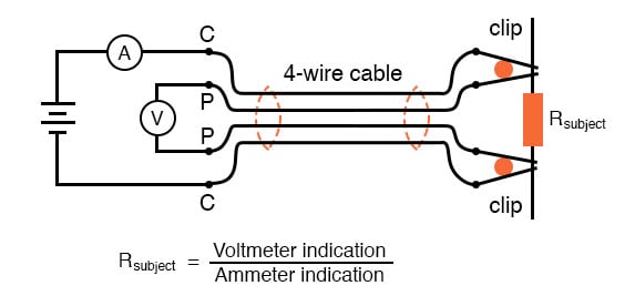
This method of measurement which avoids errors caused by wire resistance is called the Kelvin, or 4-wire method. Special connecting clips called Kelvin clips are made to facilitate this kind of connection across a subject resistance:
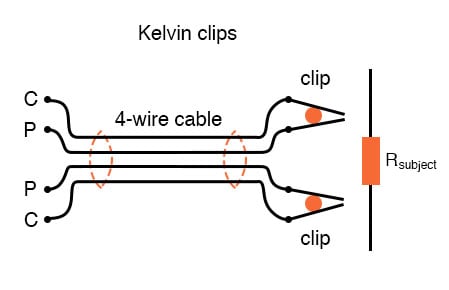
In regular, “alligator” style clips, both halves of the jaw are electrically common to each other, usually joined at the hinge point. In Kelvin clips, the jaw halves are insulated from each other at the hinge point, only contacting at the tips where they clasp the wire or terminal of the subject being measured. Thus, current through the “C” (“current”) jaw halves does not go through the “P” (“potential,” or voltage) jaw halves, and will not create any error-inducing voltage drop along their length:
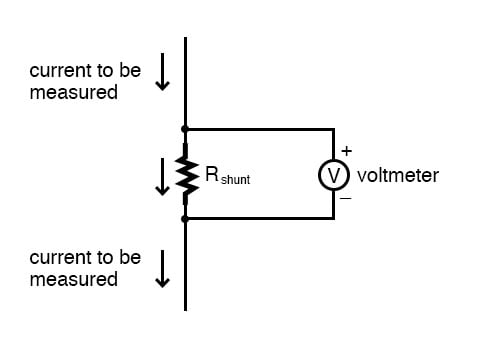
The same principle of using different contact points for current conduction and voltage measurement is used in precision shunt resistors for measuring large amounts of current. As discussed previously, shunt resistors function as current measurement devices by dropping a precise amount of voltage for every amp of current through them, the voltage drop being measured by a voltmeter. In this sense, a precision shunt resistor “converts” a current value into a proportional voltage value. Thus, current may be accurately measured by measuring voltage dropped across the shunt:
Current measurement using a shunt resistor and voltmeter is particularly well-suited for applications involving particularly large magnitudes of current. In such applications, the shunt resistor’s resistance will likely be in the order of milliohms or microohms, so that only a modest amount of voltage will be dropped at full current.
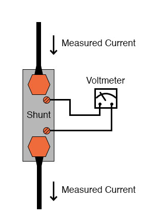
Resistance this low is comparable to wire connection resistance, which means voltage measured across such a shunt must be done so in such a way as to avoid detecting voltage dropped across the current-carrying wire connections, lest huge measurement errors be induced. In order that the voltmeter measure only the voltage dropped by the shunt resistance itself, without any stray voltages originating from wire or connection resistance, shunts are usually equipped with four connection terminals:
In metrological (metrology = “the science of measurement”) applications, where accuracy is of paramount importance, highly precise “standard” resistors are also equipped with four terminals: two for carrying the measured current, and two for conveying the resistor’s voltage drop to the voltmeter. This way, the voltmeter only measures voltage dropped across the precision resistance itself, without any stray voltages dropped across current-carrying wires or wire-to-terminal connection resistances.
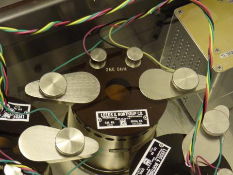
The following photograph shows a precision standard resistor of 1 Ω value immersed in a temperature-controlled oil bath with a few other standard resistors. Note the two large, outer terminals for current, and the two small connection terminals for voltage:
Here is another, older (pre-World War II) standard resistor of German manufacture. This unit has a resistance of 0.001 Ω, and again the four terminal connection points can be seen as black knobs (metal pads underneath each knob for direct metal-to-metal connection with the wires), two large knobs for securing the current-carrying wires, and two smaller knobs for securing the voltmeter (“potential”) wires:
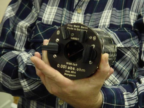
Appreciation is extended to the Fluke Corporation in Everett, Washington for allowing me to photograph these expensive and somewhat rare standard resistors in their primary standards laboratory.
It should be noted that resistance measurement using both an ammeter and a voltmeter is subject to compound error. Because of the accuracy of both instruments factors into the final result, the overall measurement accuracy may be worse than either instrument considered alone. For instance, if the ammeter is accurate to +/- 1% and the voltmeter is also accurate to +/- 1%, any measurement dependent on the indications of both instruments may be inaccurate by as much as +/- 2%.
Greater accuracy may be obtained by replacing the ammeter with a standard resistor, used as a current-measuring shunt. There will still be a compound error between the standard resistor and the voltmeter used to measure voltage drop, but this will be less than with a voltmeter + ammeter arrangement because typical standard resistor accuracy far exceeds typical ammeter accuracy. Using Kelvin clips to make a connection with the subject resistance, the circuit looks something like this:
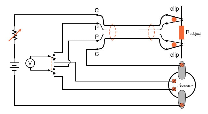
All current-carrying wires in the above circuit are shown in “bold,” to easily distinguish them from wires connecting the voltmeter across both resistances (Rsubject and Rstandard). Ideally, a potentiometric voltmeter is used to ensure as little current through the “potential” wires as possible.
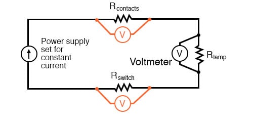
The Kelvin measurement can be a practical tool for finding poor connections or unexpected resistance in an electrical circuit. Connect a DC power supply to the circuit and adjust the power supply so that it supplies a constant current to the circuit as shown in the diagram above (within the circuit’s capabilities, of course). With a digital multimeter set to measure DC voltage, measure the voltage drop across various points in the circuit.
If you know the wire size, you can estimate the voltage drop you should see and compare this to the voltage drop you measure. This can be a quick and effective method of finding poor connections in wiring exposed to the elements, such as in the lighting circuits of a trailer. It can also work well for unpowered AC conductors (make sure the AC power cannot be turned on).
For example, you can measure the voltage drop across a light switch and determine if the wiring connections to the switch or the switch’s contacts are suspect. To be most effective using this technique, you should also measure the same type of circuits after they are newly made so you have a feel for the “correct” values. If you use this technique on new circuits and put the results in a log book, you have valuable information for troubleshooting in the future.
RELATED WORKSHEETS:

In Partnership with Future Electronics


by Jake Hertz

by Jake Hertz

by Duane Benson

