 Facebook
 Google
 GitHub
 Linkedin
Capturing IMU Data with a BNO055 Absolute Orientation Sensor
The BNO055 is an absolute orientation sensor from Bosch that combines sensor data and a microprocessor to filter and combine the data, giving users their absolute orientation in space.
The Bosch BNO055 combines tri-axis accelerometers, gyroscopes, and magnetometers to provide orientation to users.
About the Sensor
The BNO055 uses three triple-axis sensors to simultaneously measure tangential acceleration (via an accelerometer), rotational acceleration (via a gyroscope), and the strength of the local magnetic field (via a magnetometer). Data can then be either sent to an external microprocessor or analyzed inside the sensor with an M0+ microprocessor running a proprietary fusion algorithm. Users then have the option of requesting data from the sensor in a variety of formats.
The chip also has an interrupt that can notify the host microcontroller when certain motion has occurred (change in orientation, sudden acceleration, etc.).
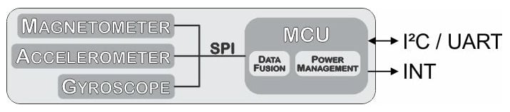
Re-created block diagram from datasheet
The sensor must be calibrated prior to use and a read register holds the current calibration status. Once calibrated, the calibration offsets can be written to the sensor and then the sensor is immediately ready to use the next time it is powered on.
See the video below to learn how to calibrate your sensor.
A host microcontroller can request any or all of the data from the sensors (accelerometer, gyroscope, and/or magnetometer) in non-fusion mode and can request absolute and relative orientation (angles or quaternions) in fusion mode.
The sensor can return acceleration in m/s² or mg ($$1 mg=9.81\frac{m}{s^2}\times 10^{-3}$$); magnetic field strength in mT; gyroscope data in degrees or radians per second (DPS and RPS, respectively), Euler angles in degrees or radians, or quaternions; and temperature in °C or °F. All options are set in the unit_selection register (table 3-11 in the datasheet, PDF page 30).
Euler Angles vs. Quaternions
If you are designing a sensor solution for a system that has a limited range of motion, you can use Euler angles. But if you are designing a sensor that can be oriented anywhere in space, you should use quaternions.
Euler Angles
Euler angles allow for simple visualization of objects rotated three times around perpendicular axes (x-y-x, x-z-x, y-x-y, y-z-y, z-x-z, z-y-z, x-y-z, x-z-y, y-x-z, y-z-x, z-x-y, z-y-x).
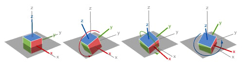
x-y-z rotations from Wolfram.com
As long as the axes stay at least partially perpendicular, they are sufficient. However, as the axes rotate, an angle exists where two axes can describe the same rotation—creating a condition known as gimbal lock. When gimbal lock occurs, it is impossible to reorient without an external reference. See my article, Don't Get Lost in Deep Space: Understanding Quaternions, to learn more about gimbal lock.
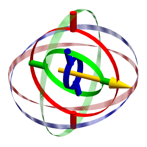
This animation has three gimbals (shown as red, green, and blue solid cylinder segments) along with the available rotations (shown as red, green, and blue transparent spherical lunes). When the plane of the internal green gimbal aligns with the plane of the red gimbal, the axes of rotation of the red and blue gimbals overlap and gimbal lock occurs (indicated by a light-yellow background).
The problem of gimbal lock does not exist when using quaternions.
Quaternions
Quaternions were invented by William Hamilton in 1843 as a way to multiply and divide three numbers. They slowly fell out of favor over the course of many decades and saw a revitalization in the nuclear era and again with modern computer graphics programming. A quaternion consists of four numbers: a scalar and a three-component vector.
 .
.
where w, x, y, and z are all real numbers and i, j, and k are quaternion units.
Typically, w, x, y, and z are kept in the range between -1 and 1, and $$\sqrt{w^2+x^2+y^2+z^2}=1$$.
These four numbers succinctly reorient vectors in a single rotation with or without changes in length.
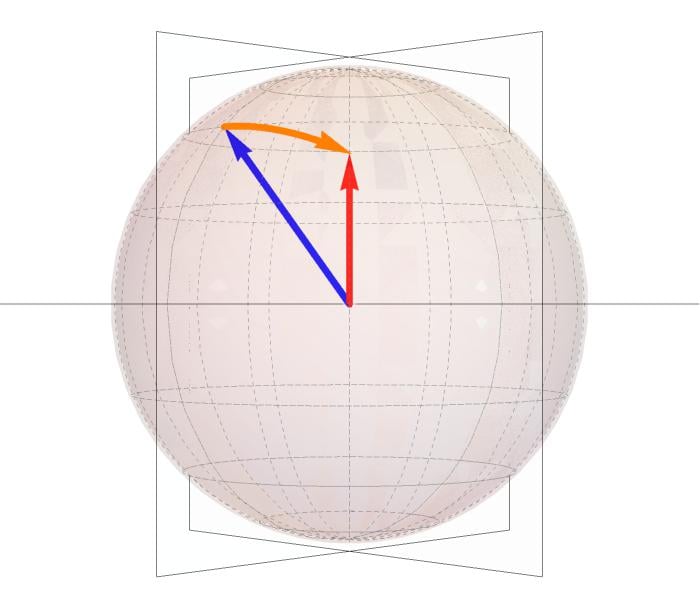
The blue and red vectors are of unit length. The orange is the rotation required to rotate the blue vector into the red.
Normal transformation matrices consist of nine numbers and involve the application of trigonometric functions. Quaternions consist of four numbers, all less than or equal to one. It is possible to convert a quaternion to an orthogonal transformation matrix but, due to the mathematical properties associated with gimbal lock (again, see my quaternion article for more information), it is slightly more difficult to convert from rotation matrix to a quaternion.
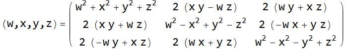
Method of converting a quaternion to a 3x3 orthogonal rotation matrix.
The code snippets below demonstrate how to create a 3×3 transformation matrix and roll, pitch, and yaw angles from a quaternion.
/* Create Rotation Matrix rm from Quaternion */
double rm[3][3];

rm[1][1] = quat.w()*quat.w() + quat.x()*quat.x() - quat.y()*quat.y() - quat.z()*quat.z();
rm[1][2] = 2*quat.x()*quat.y() - 2*quat.w()*quat.z();
rm[1][3] = 2*quat.x()*quat.z() + 2*quat.w()*quat.y();
rm[2][1] = 2*quat.x()*quat.y() + 2*quat.w()*quat.z();
rm[2][2] = quat.w()*quat.w() - quat.x()*quat.x() + quat.y()*quat.y() - quat.z()*quat.z();
rm[2][3] = 2*quat.y()*quat.z() - 2*quat.w()*quat.x();
rm[3][1] = 2*quat.x()*quat.z() - 2*quat.w()*quat.y();
rm[3][2] = 2*quat.y()*quat.z() + 2*quat.w()*quat.x();
rm[3][3] = quat.w()*quat.w() - quat.x()*quat.x() - quat.y()*quat.y() + quat.z()*quat.z();

/* Display Rotation Matrix */
Serial.print(rm[1][1],5);Serial.print("  \t");
Serial.print(rm[1][2],5);Serial.print("  \t");
Serial.println(rm[1][3],5);
Serial.print(rm[2][1],5);Serial.print("  \t");
Serial.print(rm[2][2],5);Serial.print("  \t");
Serial.println(rm[2][3],5);
Serial.print(rm[3][1],5);Serial.print("  \t");
Serial.print(rm[3][2],5);Serial.print("  \t");
Serial.println(rm[3][3],5);

/* Create Roll Pitch Yaw Angles from Quaternions */
double yy = quat.y() * quat.y(); // 2 Uses below

double roll = atan2(2 * (quat.w() * quat.x() + quat.y() * quat.z()), 1 - 2*(quat.x() * quat.x() + yy));
double pitch = asin(2 * quat.w() * quat.y() - quat.x() * quat.z());
double yaw = atan2(2 * (quat.w() * quat.z() + quat.x() * quat.y()), 1 - 2*(yy+quat.z() * quat.z()));

/*  Convert Radians to Degrees */
float rollDeg  = 57.2958 * roll;
float pitchDeg = 57.2958 * pitch;
float yawDeg   = 57.2958 * yaw;

/*  Display Roll, Pitch, and Yaw in Radians and Degrees*/
Serial.print("Roll:");  Serial.print(roll,5);  Serial.print(" Radians \t"); Serial.print(rollDeg,2);  Serial.println(" Degrees");
Serial.print("Pitch:"); Serial.print(pitch,5); Serial.print(" Radians \t"); Serial.print(pitchDeg,2); Serial.println(" Degrees");
Serial.print("Yaw:");   Serial.print(yaw,5);   Serial.print(" Radians \t"); Serial.print(yawDeg,2);   Serial.println(" Degrees");
Interfacing the Sensor with Arduino
I purchased the BNO055 sensor affixed to a development board with support components from Adafruit. It is possible to save a bit of money by purchasing the BNO055 from Digi-Key or Mouser and soldering it to a 7.5×4.4mm 28-pin LGA to DIP converter for prototyping on a solderless breadboard. But for the marginal cost savings after shipping, I wouldn't recommend it.
To get started interfacing your BNO055 with an Arduino, follow these steps:
- Connect power, ground, SDA, and SCL
- Open the Arduino IDE and click on Sketch→Include Library→Manage Libraries
- Search for and install "Adafruit BNO055" and "Adafruit Sensor"
- Open and edit File→Examples→Adafruit BNO055→Raw Data to comment out the Euler angle section and uncomment the Quaternion section, or copy and paste the abridged code below.
#include
#include
#include
#include

/*
This program is an abridged version of Adafruit BNO055 rawdata.ino available after installing the Adafruit BNO055 library
File→Examples→Adafruit BNO055→Raw Data
  Connections on Arduino Uno
  =========================================================================
  SCL to analog 5 | SDA to analog 4 | VDD to 3.3V DC | GND to common ground
*/

#define BNO055_SAMPLERATE_DELAY_MS (100)          // Delay between data requests

Adafruit_BNO055 bno = Adafruit_BNO055();          // Create sensor object bno based on Adafruit_BNO055 library

void setup(void)
{
  Serial.begin(115200);                           // Begin serial port communication
  if(!bno.begin())                                // Initialize sensor communication
  {
    Serial.print("Ooops, no BNO055 detected ... Check your wiring or I2C ADDR!");
  }
  delay(1000);
  bno.setExtCrystalUse(true);                     // Use the crystal on the development board
}

void loop(void)
{
  imu::Quaternion quat = bno.getQuat();           // Request quaternion data from BNO055

  Serial.print(quat.w(), 4);  Serial.print("\t"); // Print quaternion w
  Serial.print(quat.x(), 4);  Serial.print("\t"); // Print quaternion x
  Serial.print(quat.y(), 4);  Serial.print("\t"); // Print quaternion y
  Serial.print(quat.z(), 4);  Serial.println();   // Print quaternion z

  delay(BNO055_SAMPLERATE_DELAY_MS);              // Pause before capturing new data
}
The program simply communicates with the BNO055 over I²C and streams the data back to the computer over a UART port. Quaternion data is sent back as tab-separated data with newlines after each quaternion.
Keep in mind that until your sensor is calibrated, your data is not valid.
Sample Quaternion Data
For the following example, I requested quaternion data from the BNO055 as I placed it in a random orientation near my desk. You can interpret the data manually at WolframAlpha.com by entering it as comma separated values enclosed in parenthesis after the word quaternion (e.g., "Quaternion(0.403, 0.414, 0.085, 0.812)")
| W | X | Y | Z |
|---|---|---|---|
| 0.40344238 | 0.41363525 | 0.08508301 | 0.81176757 |
The numbers above are a quaternion that describes the current orientation of the sensor with respect to the reference orientation.
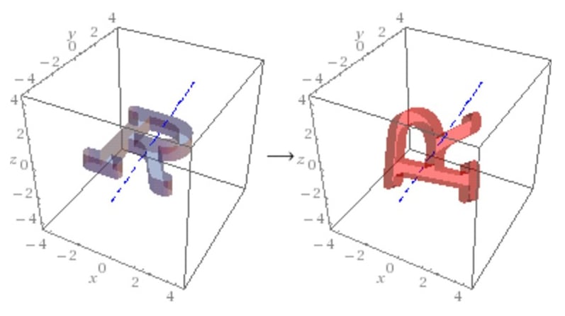
Image from WolframAlpha.com shows default and actual orientation of object
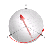
Image from WolframAlpha.com shows rotation axis and amount of rotation needed to reach the current position from the default position.
While it's certainly not necessary to look to the Internet to process your quaternion data, it is nice to have the option to double-check your work.
Capturing Data with Mathematica
Mathematica is a versatile computer program that can process almost any data you can imagine. For those interested, I put together a few lines of code that demonstrate how to receive data from a device and how to use Mathematica to evaluate the data with a few quaternion-based functions. The code below was written for Windows, so Linux and Mac users might have to change the input device line (the line that begins bConnect).
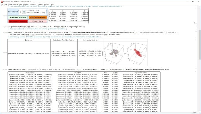
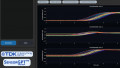
Screenshot of the Mathematica Notebook available via the download button below
Mathematica allows data to be collected and processed in real-time and after the fact. For this demonstration, I opted for a program that collects the data from the serial buffer, converts it to a rotation matrix, and uses the rotation matrix to reorient an arrow in a reference sphere.
Begin by clicking "Connect Arduino" and then "Data from Buffer." I didn't incorporate any data validation or error checking, so if the data area is blank or misformatted, the only option is to recollect the data.
Mathematica is capable of reading and working with data as it arrives over the serial port, but for this demonstration, the 30 or so measurements stored in the buffer should be sufficient to see how the program works.

Data sent from the BNO055 is analyzed in Mathematica and used to reorient an arrow in a reference sphere
Controlling a Two-Axis Gimbal
The BNO055 is well-suited for robotics use. As an example application, I'll use the BNO055 to control a laser mounted on a servo-based two-axis gimbal. The code should allow the seamless introduction of a third axis-of-rotation for any reader fortunate enough to have one.
Connect the BNO055 as before and add servos, connected to digital pins 9-11. If you're using the gimbals to hold a camera, consider upgrading to the Alorium XLR8 board. Servos rely on precise timing, and if the Arduino is processing competing tasks, it can lead to jitter. The XLR8 is a drop-in replacement of the Arduino made from an FPGA. It has a library that can control the servos from a separate "XLR8tor" (accelerator) block for steady and fluid servo movement.
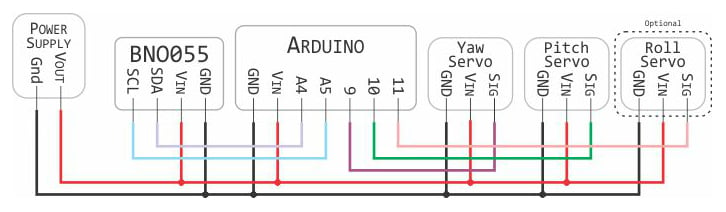
Wiring overview of the circuit
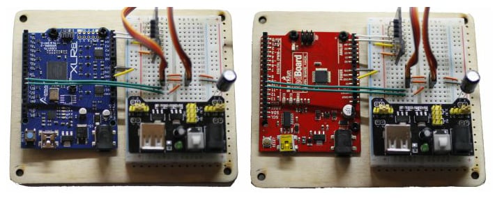
Arduino Uno R3 replacements: XLR8 vs Sparkfun "Redboard" Arduino Uno R3
//---- Included Libraries ----//
#include                            // I²C library
#include                            // trig functions
#include                 // Base library for sensors
#include                 // BNO055 specific library
#include                // Vector, Matrix, and IMUMath library
//#include                         // Standard Servo library
#include                       // XLR8 servo library
#include                       // XLR8 accelerated floating point math

#define BNO055_SAMPLERATE_DELAY_MS (50)     // Set pause between samples

//---- Variable Declaration ----//

boolean debug = true;                       // true/false = extra/no information over serial

int rollPin  = 9;                           // Digital pin for roll
int yawPin   = 10;                          // Digital pin for yaw
int pitchPin = 11;                          // Digital pin for pitch

float roll, pitch, yaw;                     // Variable to hold roll, pitch, yaw information

Adafruit_BNO055 bno = Adafruit_BNO055();    // Use object bno to hold information

Servo rollServo;                            // Create servo rollServo
Servo pitchServo;                           // Create servo pitchServo
Servo yawServo;                             // Create servo yawServo

void setup(void) {

  rollServo.attach(rollPin);                // The rollServo is connected at rollPin
  pitchServo.attach(pitchPin);              // The pitchServo is connected at pitchPin
  yawServo.attach(yawPin);                  // The yawServo is connected at yawPin

  Serial.begin(115200);                     // Create serial connection at 115,000 Baud

  if (!bno.begin())                         // Attempt communication with sensor
  {
    Serial.print("Ooops, no BNO055 detected ... Check your wiring or I2C ADDR!");
  }

  delay(100);                               // Wait 0.1 seconds to allow it to initialize
  bno.setExtCrystalUse(true);               // Tell sensor to use external crystal
}

//---- Main Program Loop ----//
void loop() {

  //---- Request Euler Angles from Sensor ----//
  imu::Vector<3> euler = bno.getVector(Adafruit_BNO055::VECTOR_EULER);

  if (debug) {                             // If debug is true, send information over serial
    Serial.print("Measured Euler Roll-Pitch-Yaw");
    Serial.print("\t   yaw: "); Serial.print(euler.x()); Serial.print("\t");
    Serial.print("\t pitch: "); Serial.print(euler.z()); Serial.print("\t");
    Serial.print("\t  roll: "); Serial.print(euler.y()); Serial.println();
  }
  /* Remap information from the sensor over the 0° - 180° range of the servo
     The Yaw values are between 0° to +360°
     The Roll values are between -90° and +90°
     The Pitch values are between -180° and +180°
  */
  int servoYaw   = map(euler.x(),   0, 360, 0, 180);
  int servoRoll =  map(euler.y(),  -90, 90, 0, 180);
  int servoPitch = map(euler.z(), -180, 180, 0, 180);

  if (debug) {                             // If debug is true, send information over serial
    Serial.print("Measured Euler Roll-Pitch-Yaw");
    Serial.print("\t   Yaw Servo: "); Serial.print(servoYaw);   Serial.print("\t");
    Serial.print("\t Pitch Servo: "); Serial.print(servoPitch); Serial.print("\t");
    Serial.print("\t  Roll Servo: "); Serial.print(servoRoll);  Serial.println();
  }
  // If debug is true, send information over serial
  if (debug) {
    Serial.println("Calculated Servo Roll-Pitch-Yaw");
    Serial.print("\t roll:");  Serial.print(servoRoll, DEC);  Serial.print("\t");
    Serial.print("\t pitch:"); Serial.print(servoPitch, DEC); Serial.print("\t");
    Serial.print("\t yaw:");   Serial.print(servoYaw, DEC);   Serial.println();
  }

  rollServo.write(servoRoll);              // Send mapped value to rollServo
  pitchServo.write(servoPitch);            // Send mapped value to rollServo
  yawServo.write(servoYaw);                // Send mapped value to rollServo

  delay(BNO055_SAMPLERATE_DELAY_MS);       // Wait before rerunning loop
}
Check out my project in action below:
Conclusion
The BNO055 is an easy-to-use inertial measurement unit that could be incorporated into a wide variety of applications, from robot stabilization (quadcopter, inverted pendulum, etc.) to camera stabilization and navigation (including dead reckoning).
Unlike other 9-DOF systems that output raw measurement data, the BNO055 filters and synthesizes data for a host microcontroller, thereby freeing up processor bandwidth and taking the guesswork out of programming.
Readers—if you would like to see a project or article that uses quaternions in greater depth, please let us know in the comment section below.
Featured image courtesy of Adafruit.
Give this project a try for yourself! Get the BOM.


Funny how this article show how good is this device but doesn’t show the complaint of people having drift over time and unstable calibration.
Yes, please, I would like to see more examples of quaternion usage.