 Facebook
 Google
 GitHub
 Linkedin
Construction of a Guitar Amplifier
This article explains the theory and the construction of the circuit of a 10W practice guitar amplifier.
A guitar amplifier is an audio electronic device that can be used to amplify the signal of a pickup attached to a guitar. By altering the tone frequencies of the instrument through an amp, the musician can control its distortion, tone, and volume.
In this article, we'll discuss how to build a homemade 10W guitar amplifier. Please note that this circuit is not meant to replace your guitar amp—a professionally-built amp will always be best for sound quality. This article is meant to serve as an educational guide to the concepts behind guitar amps and as a tutorial if you'd like to follow along building a simple amp.
Before we begin, there are a few crucial points we must discuss:
- Exercise caution before plugging in your project—make sure it's fully assembled.
- Be sure to solder an IC socket to your board so you can plug in your TL072 chip rather than soldering it directly onto the board.
- Polarity matters! The ‘tip’ of your ¼” input audio jack is the positive end and the ‘sleeve’ is negative end. Make sure you solder it correctly or you'll introduce unnecessary noise.
- You can avoid shorting the pins of your op-amp by breaking the connection of the metal strips under your TL072 chip. You can do this by scratching away the metal with the sharp tip of a pin. In order to avoid shorting the pins of the op-amp, it will be necessary to break the connection of the metal strips under the chip.
How Does a Guitar Amp Work?
The input signal input for the amplifier comes initially through a ¼” audio jack that produces a mono audio jack (meaning it doesn't differentiate between the left and right speakers audio input). The input to the audio jack comes from an electromagnetic pickup, which is made of hundreds of coils, each of which consists of resistors and inductors connected in series with one another. These resistors and inductors are, in turn, connected to a capacitor in parallel.
The guitar pickup works on the basis of Lenz’s law, which states that the direction of induced current is always opposed to the change in magnetic flux produced by the circuit. When the guitar strings of an electric guitar get magnetized by the coil, the movement of the strings produces a source voltage (Vs) which supplies an electric signal (V) to the audio jack according to Lenz’s law.
Any guitar amplifier consists of three main circuits, which we will discuss below:
- Volume
- Distortion
- Tone
Guitar Amplifier Schematic and Circuits
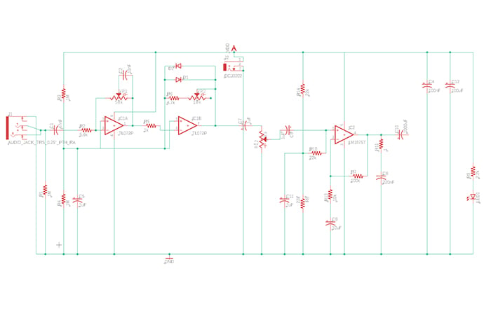
Figure 1. Guitar amplifier schematics
The Tone Circuit
The first stage of the amp is the tone circuit, which uses a dual JFET-input op-amp IC, the TL072.
As you'll see in the schematic, we have a sliding capacitor. This forms a potentiometer on the feedback loop of the op-amp.
To increase the base tone of the guitar, you can slide the capacitor to the very left position of the potentiometer. This amplifies the lower frequencies in the pickup signal.
Conversely, to increase the treble, you can slide the capacitor to the very right position of the potentiometer. This is accomplished by short-circuiting the resistor placed on the feedback loop, removing the capacitor completely. This results in the amplification of the higher frequencies in the pickup signal.
The Distortion Circuit
Distortion is an effect a musician can use to add a "fuzzy" tone to their guitar's sound, typically by increasing their gain.
In our project here, we'll create a clipping circuit by using two diodes. First, it's important to note that there are actually two types of clipping: hard and soft. Soft clipping, sometimes called overdrive, occurs when the gain and the input signal level are inversely proportional to each other. Hard clipping, on the other hand, denotes restricting the signal level within a given range. This is also known as distortion.
In the clipping process, we'll produce new frequencies that weren't part of the original audio signal. Such frequencies can be harmonics or inharmonics where the former denotes whole number multiples of the original signal's frequencies and the latter denotes more complex scenario where newer subharmonics are produced via intermodulation.
The Volume Circuit
For the volume circuit, we'll need a low-frequency class AB power amplifier, the TDA2030.
Project Construction
You may choose to use either perf board or a printed circuit board for this project. For each of the three major stages, we'll verify the guitar amplifier output. We'll use the same TL072 IC in both the tone and distortion circuits.
The ideal power input for VDD (power supply of the adapter) is 12V.
The Tone Stage
As we discussed above, the following circuit for the tone stage uses a TL072 op-amp and a 50Kohm potentiometer.

Figure 2(a). The input and tone circuit schematics
You can see the input and output of the circuit displayed on the CRO below.

Figure 2(b). Input signal and tone circuit output
Channel-A (red) = input signal form the guitar
Channel-B (yellow) = output signal of the tone circuit taken at resistor R5
The Distortion Stage
In the distortion stage, we'll need to clip the output waveform that comes from the TL072 op-amp's pin 1. As we've already covered earlier, this circuit requires two 1N4001 diodes in the clipping circuit. We'll also use a 10Kohm linear potentiometer.

Figure 3a. Distortion circuit schematics
You can see the TL072 distorted output below.

Figure 3(b). Input signal and distortion circuit output
Channel A (red): Input signal
Channel B (yellow): Distorted output signal
The Volume Stage
All we have left to do here is to amplify the distortion of the circuit output. We'll use the audio amp ICs TDA2030/TDA2050/LM386 for this final portion of the project, which connects to the speaker.
You'll notice in the schematic below that we're including an LED so we can indicate when the amp is on or off.
Here's the schematic at hand:

Figure 4(a). Volume circuit schematics
And here's the corresponding CRO output:

Figure 4(b). Input signal and volume circuit output
Channel A (red): input signal from the guitar
Channel B (yellow): Amplifier output
Note: Take a minute to check out the difference between the input signal from the beginning and the output signal above. Note the distortion and also the fact that the output voltage is double the input voltage.
BOM
| Type | Value | Qty | Markings | Directional | Direction Indicated |
|---|---|---|---|---|---|
| Resistors | 1 Mohm | 3 | brown black green | NO | |
| 5.6 kOhm | 1 | green blue red | |||
| 1 kOhm | 1 | brown black red | |||
| 22 kOhm | 3 | red red orange | |||
| 4.7 kOhm | 1 | yellow violet red | |||
| 2.2 kOhm | 1 | red red red | |||
| 100 kOhm | 1 | brown black yellow | |||
| 10 kOhm | 1 | brown black orange | |||
| 1 Ohm | 1 | ||||
| Potentiometers | 50KB pot | 1 | B50K (linear) | NO* | |
| 10KB pot | 1 | B10K (linear) | |||
| 10KA pot | 1 | A10K (logarithmic) | |||
| FIlm Capacitors | 47nF | 1 | 473 | NO | |
| 100nF | 1 | 104 | |||
| 10nF | 1 | 103 | |||
| 0.22 uF | 1 | ||||
| Aluminum Capacitors | 100uF | 1 | YES |
Stripe on negative side (shorter lead) |
|
| 1000uF | 1 | ||||
| 1uF | 4 | ||||
| 10uF | 1 | ||||
| Integrated Circuits | TL072 | 1 | See diagrams | ||
| TDA2030 | 1 | ||||
| Diodes | 1N4001 | 2 | Silver stripe = negative end | ||
| LED | red LED | 1 |
flat edge/short er lead is negative |
||
| Miscellaneous | IC socket | 1 | NO | ||
| switch | 1 | ||||
| wall power plug | 1 | ||||
| power jack | 1 | ||||
| ¼” Phono plug | 1 | YES | sleeve is negative | ||
| speaker | 1 | ||||
| perfboard | 1 |
Pin Diagrams
TL072


Figure 6. Tl072 IC and pin diagram
TDA2030


Figure 7. TDA2030 IC and pin diagram
That concludes this guitar amplifier project! Share your builds and branching projects in the comments to tell us how it went.
Related Content


you may want to re-consider the input amplifier. with just above 5kOhms input impedance, any passive electric guitar (and passive piano for that matter) will just sound dull and undefined. have the input impedance at least above 500 kOhms.
hth
This Article was very obviously written by someone who has never actually touched an Electric Guitar,
let alone actually investigated WHY Guitar Amps are built the way that they are.
For instance WHY purposefully poorly designed Tube Amps are still so widely popular for Electric Guitars.
Any Electric Guitar Player will tell you that this Amplifier sounds like total CRAP.
This Author needs to do some actual research before presenting such a ridiculous proposition as this useless circuit,
as anything even remotely useful.