Facebook
 Google
 GitHub
 Linkedin
Incorporating Microphone Functionality into a Robot System
In this article, we’ll look at a fairly straightforward circuit that enables a robot or other device to detect sound.
In this article, we’ll look at a fairly straightforward circuit that enables a robot or other device to detect sound.
Supporting Information
- Design a Custom Microcontroller Programming and Testing Board
- Custom PCB Design with an EFM8 Microcontroller
- Design a Control Board for a Romi Robot Chassis
Why?
First of all, why would you want a robot with a microphone? One idea that comes to mind is a remote-controlled device that can go where people can’t or don’t want to. Aside from the obvious invasion-of-privacy applications, you could record or analyze sounds in confined or dangerous locations.
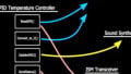
Perhaps an even more interesting application is the possibility of controlling a robot via sound waves. With some clever signal processing, you might be able to implement voice commands—you tell your robot what to do and it does it. A simpler approach would be to use constant-frequency audio signals, with each frequency corresponding to a particular action or movement. If you don’t like the “background noise” associated with this system, you could use ultrasound; Knowles, the manufacturer of the MEMS microphone discussed in this article, makes at least one mic that extends far into the ultrasonic frequency range.
MEMS Mics
In a previous article, I discussed MEMS microphones as an alternative to electret microphones. MEMS microphones are interesting simply because they use new technology, but if that’s not enough to induce you to abandon your electret circuits, here is a quick summary of the advantages:
- MEMS is supposedly capable of providing improved performance (and, in turn, this piezoelectric MEMS microphone further enhances performance compared to typical ceramic-transducer-based MEMS mics).
- MEMS is more conducive to the miniaturization that is a perpetual concern for manufacturers of consumer electronics.
- MEMS mics allow for high levels of integration, which translates into simpler circuit design.
In this article, we’ll be working with the SPU0414HR5H-SB-7 microphone from Knowles. Here are some of its characteristics:
- The sound-entry hole is on the top of the package, which is what you want for a typical parts-on-the-top-side PCB. The following diagram conveys the different arrangements used for top- and bottom-sound-hole parts.

Diagram taken from the Knowles SiSonic Design Guide.
- It has low current consumption—350 µA max.
- The flat portion of the frequency response extends from about 500 Hz to 6 kHz. Below 500 Hz the sensitivity decreases, and above 6 kHz the sensitivity increases.
- The microphone module includes all the circuitry needed to produce a buffered voltage signal corresponding to the received audio. However, the output impedance of the integrated amplifier is rather high (up to ~500 Ω); this generally isn’t a problem but it’s something to keep in mind.
- I chose a part that includes configurable amplification. This is a good idea for prototypes or experimental projects because it’s very difficult to predict the output signal levels that will result from your particular audio circumstances. The gain is set by an external resistor; I used a potentiometer for easy manual adjustments.

Diagram taken from the datasheet.
The Circuit
In the “Supporting Information” section above you have a link to an article about a control PCB that I designed specifically for the Romi robot chassis from Pololu. You can download the full schematic and BOM by clicking on the following link:
RomiRobotControlBoard_schematic_and_BOM.zip
The board includes a MEMS mic; here is the relevant portion of the schematic:

And here is the layout:

C26: I’m using this capacitor to create an RC low-pass filter for the audio output signal—I provide the C, and the output impedance of the mic’s internal amplifier provides the R. This audio signal will be digitized, so as usual we should have an anti-aliasing filter. Ideally, you would design the anti-aliasing filter according to the ADC sampling frequency, but I didn’t have a specific sampling frequency in mind when I designed the board so I just chose a cutoff frequency up toward the end of the audio range. If we assume that the output impedance of the microphone module is 500 Ω, the cutoff frequency will be
$$f_c=\frac{1}{2\pi RC}=\frac{1}{2\pi(500\ \Omega)(0.022\ \mu F)}\approx14.5\ kHz$$
TP1: I had a feeling that I would want to probe the microphone’s output signal, so I added a test point:

These little surface-mount test points are very handy. They don’t take up much space and they allow you to easily clip on a scope probe.
POT1 and C25: These two components work together to establish the gain. The actual magnitude of the gain is dependent only on the resistance of POT1 (the formula is given in the datasheet, page 6). The nominal range of this potentiometer is 200 Ω to 10 kΩ. This means that I can vary the mic’s gain from ~2.8× (at 10 kΩ) to ~9.5× (at 200 Ω); if you prefer logarithms, that’s ~9 dB to ~20 dB.
So then why do we need C25? Well, the mic module is a single-supply device, and the output has a DC offset. Without C25, the gain would apply to the DC offset as well, such that even relatively small gains would result in saturation. So C25 is a feedback-loop DC-blocking capacitor that allows the gain to be unity at DC and greater than unity at higher frequencies. However, the transition from unity gain to the high-frequency gain isn’t abrupt; you’re actually forming a high-pass filter, with a corner frequency given by the equation on page 6 of the datasheet.
Important Note: The SiSonic design guide (page 8) shows an additional series capacitor connected to the mic’s output pin. This cap removes the output’s DC offset, and it’s included in the diagrams as though it should be present in every circuit—but that is not the case! Apparently the people who created the design guide were assuming that you would be using the microphone in the context of a typical AC-coupled audio circuit. But if the output signal is going to the input of a single-supply ADC (such as the ADC inside my single-supply microcontroller), you need the DC offset, because the ADC can’t digitize voltages below ground.
Testing the Mic
In the following video you can see the output from the MEMS microphone reacting to different notes produced by my wooden flute. The voltage scale is 100 mV per division, so the larger signals are up above 200 mV peak-to-peak; the DC offset is around 1 V.
In the next video I am using my computer to generate a constant-frequency tone while using the potentiometer to vary the gain from maximum to minimum. (At least I think I went from maximum to minimum . . . the potentiometer was giving me trouble and I think I broke it while recording this video or shortly thereafter.)
Conclusion
We discussed some reasons for why you might want to include a microphone in your robot system, and we looked at a particular MEMS microphone and its support circuitry. What we’ve done here is not particularly exciting, but it is in fact a significant accomplishment, since the output signal shown on the scope is ready for direct connection to a typical single-supply microcontroller ADC, and there are all sorts of things that you can do with the audio data once you have it digitized.
Give this project a try for yourself! Get the BOM.