 Facebook
 Google
 GitHub
 Linkedin
How to Write Assembly Language: Basic Assembly Instructions in the ARM Instruction Set
Learn some basic instructions used in the ARM instruction set used for programming ARM cores.
Learn some basic instructions used in the ARM instruction set used for programming ARM cores.
This article is intended to help you learn about basic assembly instructions for ARM core programming.
We will pick up from a previous post on ARM register files—please consider reviewing that information before continuing as we will reference register denotations and register flags in the instructions below.
This information will be used in the next article to program a Raspberry Pi, which uses a 32-bit ARM core. In this article, we will focus our attention on 32-bit ARMv7 instructions and 32-bit registers.
Note: Later versions of the Raspberry Pi, running Raspbian, use a 64-bit ARMv8 processor, but run it in 32-bit mode just like the older v7 versions. We may cover ARMv8 in a future article.
Supporting Information:
- What Is a Microarchitecture? Understanding Processors and Register Files in an ARM Core
- The Electrical Engineer’s Guide to Instruction Set Architectures (ISAs)
- A Rundown of x86 Processor Architecture
Machine Code
Instructions are used by the processor—let's take one look at the machine code that the instructions represent. Since most of the instructions we'll go over are for data operations, I've grabbed the data-processing instruction out of the ARMV7 manual.
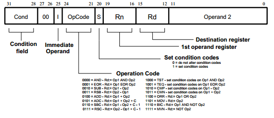
Figure 1. ARM data-processing instruction
Figure 1 shows the 32 bits found in an ARM data-processing instruction; each bit has a specific purpose, either individually or as part of a group.
The condition field is 4 bits wide, as there are roughly fifteen conditional codes. The opcode is 4 bits wide and sits between the immediate flag, which signals that operand 2 holds an immediate value, and the condition-set flag, which we can use to update the status register during an operation (more on these later). Notice it's the opcode that determines the operation—such as addition, subtraction, or exclusive OR—that the processor will perform.
As you go through the instructions below, we'll reference Figure 1 and try to see how the assembly instruction gets encoded into binary. And don't be afraid to dig through the ARM manual for more information.
How to Read Assembly Instructions: Mnemonics and Operands
Every instruction begins with a mnemonic that represents an operation. Following the mnemonic are the operands that will be operated on. These are typically destination and source operands, as seen below.
MNEMONIC DEST, SRC1, SRC2
The ADD instruction (covered in the section below) adds R2 to R1 and puts the result in register R0 (see the previous article for an explanation of these denotations). This is the typical way to read an assembly instruction. Add R2 to R1 and put it (the result) in R0. The equivalent machine code that will execute on the processor is shown alongside the ADD instruction.
The 'Cond' field contains '1110' for always execute. These bits come into play when using conditional suffixes appended to the ADD operation. The next field is unused and set to zero. The 'I' field is zero because 'Op2' is a register and not an immediate value. The 'S' field is zero because we did not append an S to the ADD operation, i.e., we don't want this instruction to update the status register flags (N, Z, C, and V, discussed above).
If you refer back to Figure 1, notice the opcode for addition. It's 0100b. This tells the processor to set the datapath for an ADD operation. The last three fields are R1 (0001b), R0 (0000b), and R2 ( ….0010b).
Cond I OpCd S Rn Rd Op2
ADD R0, R1, R2 @ 1110|00|0|0100|0|0001|0000|000000000010
The operands in an instruction are typically registers, but they can also be memory addresses or immediate values. An immediate value is an exact number to be used. These are prefixed with a # symbol. For instance, instead of using R2, above, we can use the immediate value 42. This instruction is shown below:
Cond I OpCd S Rn Rd Op2
ADDS R4, R6, #42 @ 1110|00|1|0100|1|0110|0100|000000101010
This instruction adds 42 to R6 and puts the result in R4. This time around 'I' is set to 1 because we are using an immediate value for operand 2. The opcode remains the same since we're still doing addition. Notice the 'S' field is 1; so we want this ADD operation to update our status register flags during execution.
The next instruction can use the 'Cond' field to check the status flags and conditionally execute based on the result. 'Rn' is 0110b, representing R6, and 'Rd' is 0100b for R4. The immediate value in 'Op2' is the 12-bit binary representation of the number 42. The rest of this section lists a subset of the most basic ARM instructions, with a short description and example.
Instructions for Data Processing
The following instructions manipulate data. This can be arithmetic operations that perform math functions, comparison operations, or data movement.
Addition (ADD)
Addition (ADD) adds R2 to R1 and puts the result in R0. Addition with Carry (ADC) adds R2 to R1, along with the carry flag. This is used when dealing with numbers larger than a single 32 bit word.
ADD R0, R1, R2
ADC R0, R1, R2
Subtraction (SUB)
Subtraction (SUB) subtracts R2 from R1 and puts the result in R0. Subtraction with Carry (SBC) subtracts R2 from R1 and, if the carry flag is cleared, subtracts one from the result. This is equivalent to borrowing in arithmetic and ensures that multi-word subtraction works correctly.
SUB R0, R1, R2
SBC R0, R1, R2
Compare (CMP) and Compare Negative (CMN)
Compare (CMP) and Compare Negative (CMN) compare two operands. CMP subtracts R1 from R0 and CMN adds R2 to R1, and then the status flags are updated according to the result of the addition or subtraction.
CMP R0, R1
CMN R1, R2
Move (MOV)
The Move (MOV) operation does exactly what it sounds like. It moves data from one place to another. Below, R1 is copied into R0. The second line puts the immediate value 8 into R0.
MOV R0, R1
MOV R0, #8
Move Negative (MVN)
Move negative (MVN) performs a similar operation, but complements (inverts) the data first. This is useful when performing operations with negative numbers, in particular with two's complement notation. The instruction below puts NOT 8, better known as –9, into R0. Add one to that result and you have performed the two's complement and obtained -8.
MVN R0, #8
AND performs the bitwise AND of R2 and R1 and puts the result in R0. An immediate value can be used instead of R2.
AND R0, R1, R2
ORR and EOR
ORR and EOR perform the bitwise OR and XOR, respectively, of R2 and R1.
ORR R0, R1, R2
EOR R0, R1, R2
Bit Clear (BIC)
Bit Clear (BIC) performs a bitwise AND of R2 and R1, but first complements the bits in R2. This operation is often used with immediate values, as in the second line, where the immediate value, 0xFF, is inverted and subsequently ANDed with R1. ANDing eight zeros with the first byte of R1 will clear those bits, i.e., set them equal to zero, and the result will be put in R0.
BIC R0, R1, R2
BIC R0, R1, #0xFF
Test Bits (TST) and Test Equivalence (TEQ)
TeST Bits (TST) and Test Equivalence (TEQ) exist to test the bits located in registers. These instructions do not use a destination register, but simply update the status register based on the result. TST essentially performs a bitwise AND of the two operands. By using a mask for operand two, we can test if an individual bit in R0 is set.
In this case, we check bit 3 (bitmask = 1000b = 8) and set the Z flag based on the outcome. TEQ performs a similar function to exclusive or and is great for checking whether two registers are equal. This updates the N and Z flag, therefore it also works on signed numbers; N is set to one if their signs are different.
TST R0, #8
TEQ R1, R2
Multiplication (MUL)
Multiplication (MUL) multiplies R1 by R2 and puts the result in R0. Multiplication cannot be used with an immediate value.
MUL R0, R1, R2
Instructions for Shifting and Rotating
Logical Shift Left (LSL)
Logical Shift Left (LSL) shifts the bits in R1 by a shift value. In this case, the immediate value 3, and drops the most significant bits. The last bit that was shifted out is put into the carry flag, and the least significant bits are filled with zeros. Below, R1 gets shifted left by the immediate value 3, or a value between 0 and 31 in R2, and put in R0. One logical left shift multiplies a value by two. This is an inexpensive way to do simple multiplication.
LSL R0, R1, #3
LSL R0, R1, R2
Logical Shift Right (LSR)
Logical Shift Right (LSR) works in the reverse fashion as LSL and effectively divides a value by two. The most significant bits are filled with zeros, and the last least significant bit is put into the carry flag.
LSR R0, R1, #2
Arithmetic Shift Right (ASR)
Arithmetic Shift Right (ASR) performs the same work as LSR but is designed for signed numbers. It copies the sign bit back into the last position on the left.
ASR R0, R1, #4
Rotate Right (ROR)
Rotate Right (ROR) rotates all the bits in a word by some value. Instead of filling the bits on the left with zeros, the bits shifted out are simply put back into the other end.
ROR R0, R1, #5
Instructions for Branching Operations
One important function of a processor is the ability to choose between two code paths based on a set of inputs. This is exactly what branching operations do. A processor normally executes one instruction after the other by incrementing R15, the program counter (PC), by four bytes (i.e., the length of a single instruction). Branching changes the PC to another location denoted by a label that represents that part of the assembly code.
Branch (B)
Branch (B) moves the PC to an address specified by a label. The label (“loop” in the example below) represents a section of code that you want the processor to execute next. Labels are just text, usually a meaningful word.
B loop
Branch Link (BL)
Branch Link (BL) performs a similar operation, but it copies the address of the next instruction into R14, the link register (LR). This works great when performing subroutine/procedure calls, because as soon as the section of code at the label is finished we can use the LR to get back to where we branched. Below, we branch to the label “subroutine” and then use the link register to get back to the next instruction.
BL subroutine
…
subroutine:
…
…
MOV PC, LR
We use a MOV instruction to put the link register back into the program counter. This returns the program to the spot right after our subroutine call, here labeled
Instructions for Load and Store
A computer's memory stores data that is needed by the processor. This data is accessed by using an address. By first putting an address into a register, we can then access the data at that address. This is why we use load and store operations.
Load Register (LDR)
Load register (LDR) loads the data located at an address into the destination register. The brackets around R1 signify that the register contains an address. By using the brackets we put the data at that address into R0, instead of the address itself. We can also use this notation to locate data offset from a certain address, as shown on the second line. R0 would contain the data two words away from whatever address R1 contains.
LDR R0, [R1]
LDR R0, [R1, #8]
We can also use labels to represent an address, and the corresponding data can then be loaded into a register. The first line below loads the address of the label “info” into R0. The value stored at that address is then accessed and put into R1 in the second line.
LDR R0, =info
LDR R1, [R0]
Store (STR)
Store (STR) performs the complementary operation to load. STR puts the contents of a register into a memory location. The code below stores the data in R1 at the address in R0. Again, the brackets signify that R0 holds an address, and we want to modify the data at that address.
STR R1, [R0]
Load and Store Types: Byte (B), Halfword (H), Word (Omitted), Signed (SB), Unsigned (B)
Both load and store can be written with a type appended to them. This type signifies whether the instruction will manipulate a byte (B), halfword (H), or word (omitted) and whether the data is signed (SB) or unsigned (B).
One place this may come in handy is for string manipulation, as ASCII characters have a length of one byte. These operations also allow for the use of offsets when loading or storing, as seen in the last line.
LDR R0, =text @ load a 32 bit address into R0
STRB R1, [R0] @ store byte at address in memory
STRB R1, [R0, + R2] @ store byte at address + offset R2
Instructions for Conditionals
As mentioned earlier, the mnemonics used in an instruction can have optional condition codes appended to them. This allows for conditional execution.
Remember, the flags (as laid out in the previous article) are Z (zero), C (carry), N (negative), and V (overflow).
To force instructions to update the status register, an optional S can be appended to most mnemonics mentioned thus far. Once the status register is updated, a number of conditional suffixes, shown below, can be used to control whether the instruction executes. The binary codes for these suffixes correspond to the first four bits of the data-processing instruction shown above (see Figure 1).
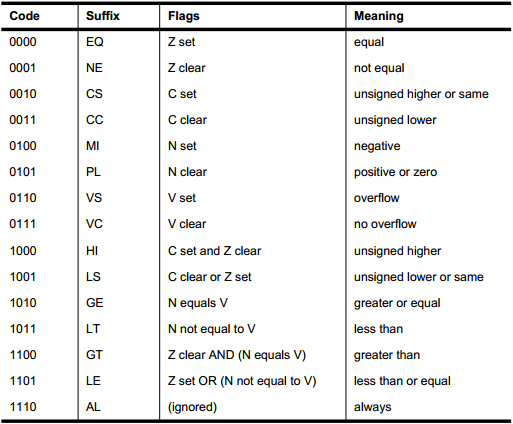
Figure 2. Condition suffixes
These suffixes are appended to the mnemonic when writing assembly. The listing below shows a few of the conditional suffixes used with instructions mentioned earlier.
Since we'll be assembling with the GNU assembler in the next article, we need to use the @ symbol to represent a comment.
.global _start
start:
MOV R0, #3 @ Put the value 3 into R0
MOV R1, #0 @ Put the value 0 into R1
loop:
CMP R0, R1 @ Compare R1 to R0 (effectively R0 minus R1)
BEQ done @ If they are equal (Z=1) branch to done label
ADDGT R1, #1 @ If R0 is greater than R1 add 1 to R1
SUBLT R1, #1 @ If R0 is less than R1 subtract 1 from R1
B loop @ Branch back and re-run loop
done:
Hopefully this article gives you a foundational understanding of the basic instructions used to program an ARM core. In the next article, we'll use this knowledge in a simple example of programming a core using a Raspberry Pi.


You should preface this by pointing out that this legacy encoding isn’t what we use now, and is completely unavailable in 64-bit code. The Thumb2 encoding is compact and variable length, and does not have condition code predicates for every instruction.
Thank you for pointing that out John but how many people read the comments first? The article is misleading by omission and should be amended or rewritten.
Thanks for the comments. The author’s original article did refer to different Arm versions, but this information was lost when the article was reorganized prior to publication. The introductory section has been modified in an attempt to avoid the confusion that you’re referring to.