Facebook
 Google
 GitHub
 Linkedin
Introduction to the RS Flip-Flop Phase Detector
Learn about this simple sequential phase detector and how it compares to the XOR gate. We'll also examine some key limitations and circuit implementations.
The previous article examined the exclusive-OR (XOR) phase detector—the most basic type of digital phase detector. In this article, we'll discuss the reset-set (RS) flip-flop phase detector. Whereas the XOR gate is a combinational circuit, this is the simplest form of sequential phase detector.
After deriving the RS detector's input-output characteristic, we'll highlight its strengths and weaknesses by comparing its response to that of the XOR detector. As we'll see, one of the main drawbacks of the RS flip-flop phase detector is its susceptibility to missing edges in the input signal.
Towards the end of the article, we'll introduce Hogge's phase detector, which is designed to overcome the missing edge problem. But before we dive in, let's take a moment to review the limitations of the phase detectors we covered earlier in this article series.
Limitations of XOR and Multiplier Phase Detectors
The input-output characteristic of the XOR phase detector is shown in Figure 1.
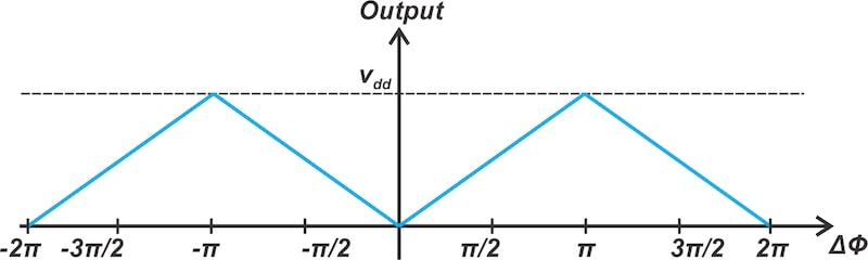
Figure 1. The XOR phase detector's output is a triangular function of the input phase difference (Δϕ).
To effectively utilize the maximum linear range of the phase detector, we typically design the system to establish a lock condition at a 90 degree phase difference between inputs, representing quadrature phase alignment. However, numerous applications demand a zero phase difference between the inputs in the lock condition.
Additionally, the XOR phase detector exhibits the same gain at both the metastable and desired equilibrium points, which may result in extended durations in the metastable state, potentially delaying the locking process. Notably, the multiplier phase detector also encounters both of these issues (quadrature phase alignment at lock and prolonged metastable states).
Sequential phase detectors can resolve these limitations by:
- Achieving zero or 180 degree phase difference at lock.
- Demonstrating significantly different gain constants between metastable and stable equilibrium states.
Additionally, certain sequential phase detectors provide a linear characteristic across phase differences exceeding 2π radians.
Now that we have some background, let's examine the simplest example of a sequential phase detector: the basic reset-set flip-flop.
The RS Flip-Flop Phase Detector
A flip-flop changes its state in response to transitions of the input signal. With an RS flip-flop phase detector, the input signals are applied to the flip-flop's set and reset inputs.
Figure 2 shows an example of an RS flip-flop. This particular circuit responds to rising edges (0 to 1).
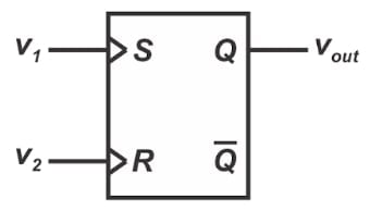
Figure 2. The RS flip-flop can serve as a phase detector.
When the S input transitions from 0 to 1, the flip-flop sets the output (Q = 1), whereas a rising edge on the R input resets the output (Q = 0). By monitoring the rising edges of the inputs, the RS flip-flop can detect the phase difference between them. We can see this by examining the input and output waveforms in Figure 3. For comparison purposes, the output waveform of an XOR gate phase detector has been included as Figure 3(d).
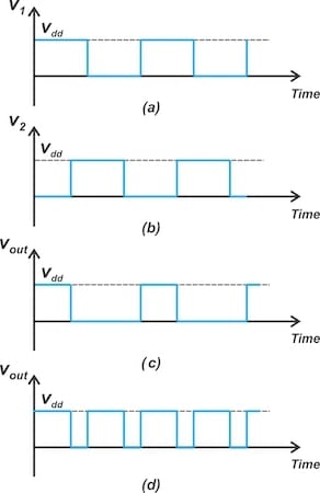
Figure 3. From top to bottom: Waveforms of input v1, input v2, the output of the RS flip-flop phase detector, and the output of the XOR phase detector.
The duty cycle of the output varies from zero to one based on the phase difference between the inputs. Therefore, much like the XOR phase detector, the average value of the output waveform represents the phase difference between the inputs. Figure 4 shows the average of the RS flip-flop phase detector's output versus the input phase difference.
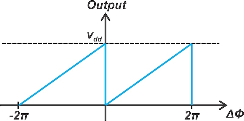
Figure 4. The RS flip-flop phase detector's input-output characteristic.
Note that the output reaches its maximum when the phase error is 2π radians. This shows that the RS flip-flop phase detector has an input phase error range twice that of the XOR phase detector.
Inspection of Figure 4 shows that the gain of this phase detector is:
$$k_d ~=~ \frac{V_{dd}}{2 \pi}$$
Equation 1.
We also see in Figure 4 that the gain at the metastable point is extremely high (ideally infinite). This means the chance of the loop staying in that state is much lower than it is for the XOR detector.
Limitations of the RS Flip-Flop Phase Detector
One drawback of this phase detector is that it requires more filtering than the XOR detector. This is because, as illustrated in Figure 3(d), the XOR phase detector produces output signals at twice the input frequency. By contrast, the RS detector's output frequency is the same as the input frequency. The lowpass filter requirements are therefore less stringent when using an XOR detector.
Note that the undesirable frequency components present at the phase detector output can degrade the VCO output spectrum. Proper filtering is required to remove them.
Finite State Machine Model of the RS Flip-Flop Phase Detector
The RS detector is a two-state device. This is illustrated by the state diagram in Figure 5.
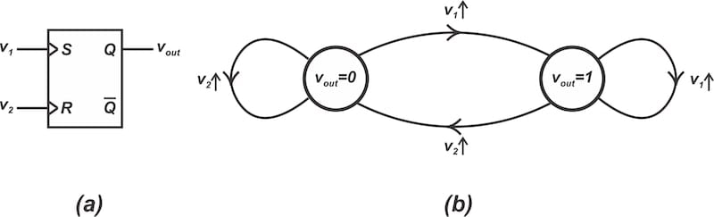
Figure 5. The RS flip-flop phase detector (a) and its equivalent-state machine (b).
In the above diagram, the upward-pointing arrow denotes a rising transition on the corresponding input. When a positive transition occurs on the set input, the system enters the vout = 1 state and remains there if further positive transitions happen on this input. However, a positive transition on the reset input takes the system from the vout = 1 state to the vout = 0 state. The system remains in the vout = 0 state if additional positive transitions occur on the reset input.
Sequential phase detectors focus solely on the transitions of the signals. Unlike the XOR detector, the duty cycle of the input signals is irrelevant when using the RS flip-flop phase detector. This means that missing or poorly defined signal transitions can lead to incorrect behavior.
Compared to either an XOR or multiplier-type phase detector, the RS detector is more vulnerable to noise. Sequential phase detectors preserve noise errors through their memory effect. This renders these circuits suitable exclusively for high signal-to-noise ratio (SNR) applications.
Circuit Implementation of the RS Flip-Flop Phase Detector
When utilizing an RS flip-flop as a phase detector, it's vital for the flip-flop to carry out set and reset operations with equal speed. If this condition is not met, the input-output characteristic will differ from the ideal one illustrated in Figure 4, indicating a static phase error. For example, the RS flip-flop using cross-coupled NOR gates presented in Figure 6 resets faster than it sets. As a result, it may not be ideal for phase detection applications.
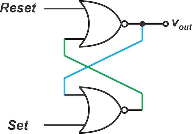
Figure 6. This RS flip-flop executes the reset operation more quickly than the set operation.
Figure 7 shows a more suitable implementation of the RS flip-flop phase detector. This configuration is capable of performing set and reset functions at equal speeds.
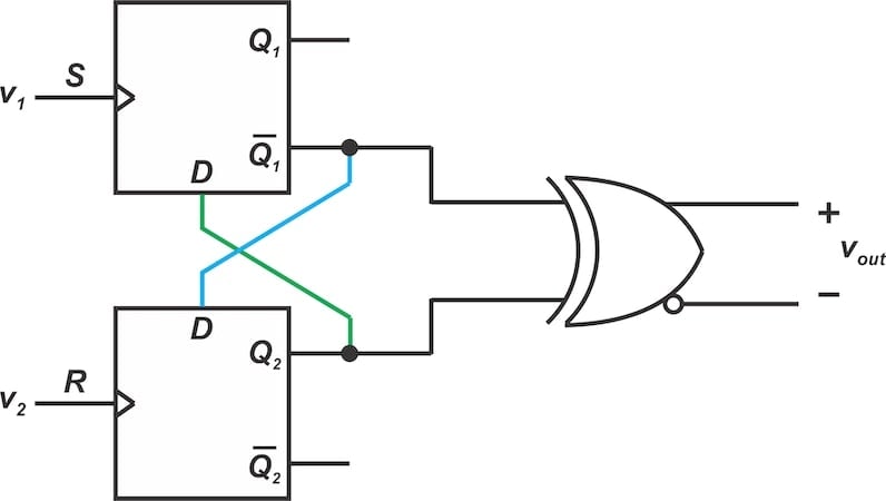
Figure 7. Circuit implementation of the RS flip-flop phase detector.
A rising edge on v1 results in Q1 being equal to Q2. Since Q2 and the inverted value of Q1 are fed into the XOR gate, the output goes HIGH, indicating the set state. Conversely, when a rising edge appears on v2, Q2 takes on the inverted value of Q1. This results in a logic-low at the XOR output, signifying the reset state.
Limitations of Sequential Phase Detectors
Most sequential phase detectors have two key limitations. For one thing, as we observed with the RS flip-flop detector, they react only to changes in the input signals. This makes them vulnerable to missing edges, although certain design modifications can help reduce this sensitivity.
A variety of inventive designs have been created to tackle the problem of sensitivity to missing edges in sequential phase detectors. Figure 8 shows one of these circuits, known as Hogge's phase detector. It operates by determining the transitions in the input data, making it less sensitive to missing edges.
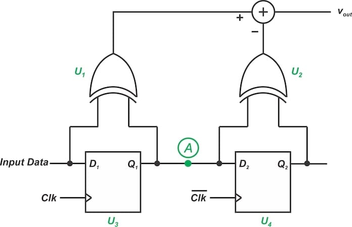
Figure 8. Hogge's phase detector.
The circuit determines the phase difference between Input Data and the clock signal denoted by Clk. To avoid sensitivity to missing edges of the input data, the circuit does nothing when input pulses are missing.
The D flip-flop U3, in conjunction with the XOR gate U1, detects transitions in the input data, generating a positive pulse at the output of U1 for each data transition. The width of these pulses depends on the phase error between the input data and the clock.
The D flip-flop U4, along with the XOR gate U2, also detects the transitions in the input data, producing a positive pulse at the output of U2 for each data transition. However, the width of these pulses is fixed and equal to half the clock period. The phase error can be determined by comparing the widths of the pulses produced by U1 and U2.
Due to space constraints, this article can't provide an in-depth explanation of Hogge's phase detector. Instead, we'll limit ourselves to a concise summary of its operational principles given above. To learn more about Hogge's phase detector, as well as other detectors that mitigate sensitivity to missing edges, please refer to the book "The Design of CMOS Radio-Frequency Integrated Circuits" by Thomas H. Lee.
Because they operate based on input transitions, sequential phase detectors introduce a sampling effect within the loop, effectively adding a time delay. This is their other key limitation. It leads to a frequency-dependent phase shift, ultimately imposing a maximum operational frequency that is significantly lower than what a non-sequential phase detector could achieve.
Wrapping Up
While XOR and multiplier phase detectors have a triangular input-output characteristic, the RS flip-flop phase detector has a sawtooth characteristic. The linear range of the RS flip-flop detector is twice that of the XOR detector. However, the RS flip-flop solution is more sensitive to noise than the XOR circuit. Being an edge-triggered circuit, it's also sensitive to missing edges.
All images used courtesy of Steve Arar
Related Content