 Facebook
 Google
 GitHub
 Linkedin
The Howland Current Pump
The Howland current pump, invented by MIT’s Professor Bradford Howland in the early 1960s, consists of an op-amp and a balanced resistor bridge and puts out current in either direction.
The Howland current pump, invented by MIT’s Professor Bradford Howland in the early 1960s, consists of an op-amp and a balanced resistor bridge and puts out current in either direction.
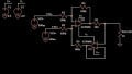
The Howland current pump, shown in Figure 1a, is a circuit that accepts an input voltage vI, converts it to an output current iO = AvI, with A as the transconductance gain, and pumps iO to a load LD, regardless of the voltage vL developed by the load itself. To see how it works, label it as in Figure 1b, and apply Kirchoff's Current Law and Ohm’s Law.
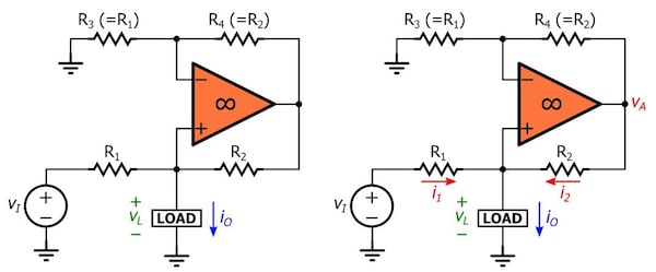
Figure 1. (a) The Howland pump. (b) Properly labeling the circuit for its analysis.
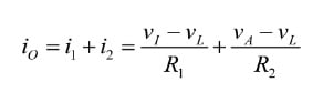
Equation 1
The op-amp, together with R3 and R4, forms a non-inverting amplifier with respect to vL, thus giving
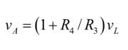
Equation 2
Substituting vA into Equation 1 and collecting, we put iO into the insightful form
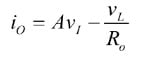
Equation 3
where A is the transconductance gain, in A/V,
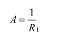
Equation 4
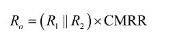
and where Ro is the output resistance presented by the circuit to the load,
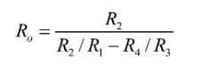
Equation 5
To make iO independent of vL we must impose Ro → ∞, or the balanced-bridge condition.
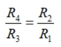
Equation 6
Take a look at the example in Figure 2 and observe, row-by-row, how the op-amp adjusts i2, via vA, so as to ensure the same current iO regardless of vL.
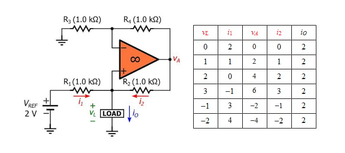
Figure 2. (a) A 2 mA current source, and (b) its inner workings for different values of vL (voltages in volts, currents in milliamps; a negative current value means that current flows in the direction opposite to the arrow).
With the polarity of VREF as shown, the pump sources iO to the load. Inverting the polarity of VREF will cause the pump to sink iO from the load. Note that for the pump to work properly vA must always be confined within the linear range of op-amp operation. If the op-amp is driven into saturation, the pump will cease to operate properly.
The Effect of Resistance Mismatches
A practical bridge is likely to be unbalanced because of resistance tolerances, so Ro is likely to be less than infinity. Denoting the tolerances of the resistances in use by p, we note that the denominator D of Equation 5 is maximized when R2 and R3 are maximized and R1 and R4 are minimized. For p << 1, we write
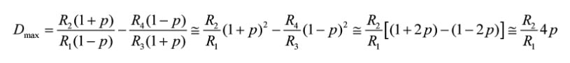
Here we have incorporated the relationship of Equation 6, applied approximation
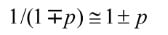
and ignored quadratic terms in p. Substituting into Equation 5 gives
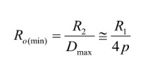
Equation 7
As an example, using 1% (p = 0.01) resistances in Figure 2a can lower Ro from ∞ to as little as 1,000/(4×0.01) = 25 kΩ, thus making iO depend upon vL, by Equation 3. If the bridge is unbalanced in the opposite direction of above, then the worst-case condition for Ro is –25 kΩ. So, depending on the mismatch, Ro may lie anywhere from +25 kΩ to ∞ to –25 kΩ.
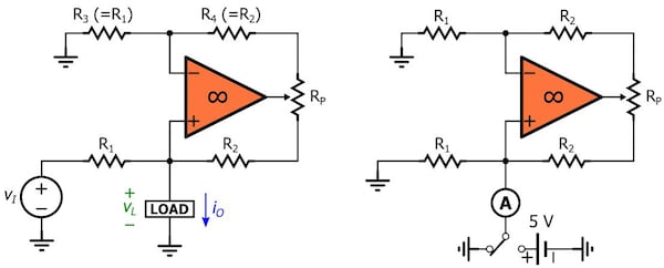
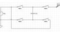
Figure 3. (a) Using a potentiometer Rp to balance the resistive bridge. (b) Calibration set up.
For improved performance, we must either use lower-tolerance resistances or balance the bridge using a potentiometer Rp, as in Figure 3a. To calibrate the circuit, ground the input as in Figure 3b and use an ammeter A. First, flip the switch to ground, and if necessary, zero the op-amp’s input offset voltage until the ammeter reads zero. Then flip the switch to a known voltage, such as 5V, and adjust Rp until the ammeter reads again zero. By imposing that iO with vL = 5 V be equal to iO with vL = 0 V, we are making iO independent of vL, in effect driving Ro to infinity, by Equation 3.
The Effect of Op-Amp Nonidealities
Common-Mode Rejection Ratio
A practical op-amp is sensitive to its common-mode input voltage, a feature that is modeled with a small internal offset voltage in series with the noninverting input. In the case of the Howland pump, this offset voltage can be expressed as vL/CMRR, where CMRR is the common-mode rejection ratio as reported in the op-amp’s datasheet. With reference to Figure 4a, we note that Equation 1 still holds, but Equation 2 changes to
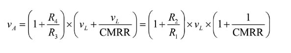
Substituting into Equation 1, solving for iO, and putting iO in the form of Equation 3 gives
Equation 8
As an example, using an op-amp with CMRR = 60 dB (=1000) in the above example will lower Ro from ∞ to (103||103)×1000 = 500 kΩ. With an arrangement of the type of Figure 3b, we can use the potentiometer to compensate for the cumulative effect of bridge imbalance as well as non-infinite CMRR.
Open-Loop Gain
So far we have assumed the op-amp to have infinite open-loop gain. The gain a of a practical op-amp is finite, so let us now see how this affects circuit behavior.
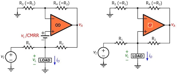
Figure 4. Circuits to investigate the effect of (a) non-infinite common-mode rejection ratio and (b) non-infinite open-loop gain.
With reference to Figure 4b, we now have
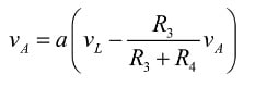
Solving for vA, substituting into Equation 1, solving for iO, and putting iO in the form of Equation 3 gives
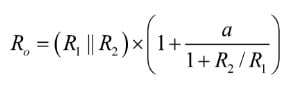
Equation 9
As an example, using an op-amp with a DC gain of 100 dB (=100,000 V/V) will lower Ro from ∞ to (103||103)×(1 + 100,000/2) ≅ 25 MΩ. With an arrangement of the type of Figure 3b, we can use the potentiometer to compensate for the cumulative effect of bridge imbalance, non-infinite CMRR, and non-infinite open-loop DC gain, and raise Ro as close as possible to ∞.
However, as we increase the frequency of operation, the gain a rolls off with frequency, leading to a progressive deterioration of Ro. For example, if an op-amp with a DC gain of 100 dB has a gain-bandwidth product of 1 MHz, its open-loop gain vs. frequency (assuming a single-pole response) will look like this:
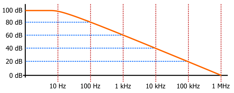
Figure 5. Single-pole frequency response of a 1 MHz op-amp with a DC open-loop gain of 100 dB.
Thus, the gain a drops to 60 dB (=1000 V/V) at 1 kHz, and the value of Ro will drop to 500×(1 + 1000/2) ≅ 250 kΩ. At 10 kHz Ro drops to 500×(1 + 100/2) ≅ 25 kΩ, and so on.
Further Reading
A Comprehensive Study of the Howland Current Pump (PDF): an application note published by Texas Instruments.
Related Content


For reducing the mismatch, how precise does my ammeter have to be? Because setting mine to 40u, current seems to be zero. Still, there’s a lot of current variation as the voltage changes.
Are you sure your op amp does not saturate or even oscillate as toy vary vL?