 Facebook
 Google
 GitHub
 Linkedin
What Is the Power Spectrum of Quantization Noise?
Our series on quantization noise begins with a clarification of the framework the author used to determine the scope of his investigation into quantization noise.
This series is a continuation of work done in two previous series. The first examined if inphase and quadrature (I/Q) combination and separation should be done analogly or digitally. The performance of I/Q modulators and demodulators, as well as of analog-to-digital converters (ADC) and digital-to-analog converters (DAC), were examined. We also discussed what makes for good performance of a communications link in this context.
ADCs and DAC are called data converters. Since not much information on the performance requirements of ADCs and DACs for modern communications waveforms was found, your author decided to look into these issues. The proper modeling of ADCs and DACs was discussed in the second series, including discussions of models that utilize ENOB (effective number of bits) and ENOB plus an intermodulation polynomial. We also went over the author's proposal for an even more effective model that included a low-pass filter.
Series Goal
In examining the performance of data converters, often the situation shown in Figure 1 is seen.

Figure 1. Simplified block diagram of a data converter's use
The total noise power out the data converter in the Nyquist bandwidth (BN) is N. The filter can be bandpass or lowpass, with bandwidth Bo. Usually, it is assumed the noise power out the filter is:
Noise power out of the filter = N(Bo / BN)
Equation 1. Note that this equation approximately holds for any reasonable filter that might follow the ADC, at any center frequency. A “reasonable filter” is one that is not too narrow.
Equation 1 assumes the noise is white, or uniform with frequency.
Your author wondered; under what conditions is this assumption, often called the pseudo quantization noise [14] assumption, true?
References [3] through [32] cover various aspects of this question. To clarify things, your author also performed some simulations of data converters with various inputs. The results are reported in this series.
He only considered uniform quantization, (all step sizes equal) since that is usually used in high-speed data converters. Also, sigma-delta converters were not considered.
For ADC applications, often the RF chain gain is made large enough so the noise from previous components is 3 to 5 dB above the quantization noise, so the quantization noise spectrum does not matter. However, this can add to system cost by requiring more RF gain, and a higher dynamic range from the ADC.
For DAC applications, hopefully, the noise from the DAC is dominant, and one does not want to add noise later in the chain just to assure the transmitted noise spectrum is white.
Peak, Average, and rms Values
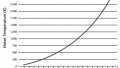
It is important to define the level of the input signal. Figure 2 shows a sine wave quantized with 5 bits. The level of this signal is usually called 0 dBFS; where FS refers to Full Scale on the quantizer. But, RF engineers usually deal with rms quantities. Since the rms value of a sine wave is 3 dB below the peak value, the sine wave of Figure 2 is at -3 dBrmsFS, or 0 dBpeakFS.

Figure 2.
For the rest of this series, signal levels will be specified in dBrmsFS or dBpeakFS,
Note also that, since power is the square of the voltage, the Peak-to-Average Power Ratio (PAPR) of this constant envelope sine wave is 3 dB. In fact, the PAPR of all bandpass phase or frequency modulated constant-envelope signals, such as MSK, is 3 dB.
“WAIT A MINUTE!” you might say, Dear Reader. “Isn’t the PAPR of a constant-envelope signal such as MSK 0 dB? That is what people call it.”
In fact, when people refer to the PAPR in this manner, they are referring to the ratio of the peak power of the envelope to the average power of the envelope. In particular, this reference to PAPR is used when characterizing the complex envelope [33] of a signal. Since we are concerned with real voltages in this series, the PAPR will be the power in the real peak divided by the power in the real average. This PAPR will be 3 dB higher than the one usually quoted.
In the next article, we'll move on to discussing the spectrum of analog-to-digital converter (ADC) outputs.
Abbreviations Used
Please use the following table for the remainder of the series.

References
The following references will be used throughout the remainder of the series, as well:
Introduction and Motivation
[1] Digital or Analog? How Should I and Q Combining and Separation Be Done?
Requirements for Good Communications Link Performance: IQ Modulation and Demodulation
[2] How Should Data Converters Be Modeled for System Simulations?
Modeling ADCs Using Effective Number of Bits (ENOB)
Modeling ADCs Using Intermodulation Polynomial and Effective Number of Bits
Adding a Low-pass Filter to an ADC Model and DAC Modeling
Quantization noise with or without clipping effects
ADC & DAC
[3] Maloberti, Franco; Data Converters; Springer Publishing; 2007
ADC Specific, with and without Clipping Effects
[4] Lever, K. V.; Cattermol, K.W., "Quantising noise spectra," Electrical Engineers, Proceedings of the Institution of , vol.121, no.9, pp.945,954, September 1974
Lever, K.V.; Cattermole, K.W., "Erratum: Quantising noise spectra," Electrical Engineers, Proceedings of the Institution of, vol.122, no.3, pp.272, March 1975
[5] Gersho, A, "Principles of quantization," Circuits and Systems, IEEE Transactions on, vol.25, no.7, pp.427, 436, Jul 1978
[6] Gersho, A, "Quantization," Communications Society Magazine, IEEE, vol.15, no.5, pp.16, 16, September 1977
[7] Schuchman, L., "Dither Signals and Their Effect on Quantization Noise," Communication Technology, IEEE Transactions on, vol.12, no.4, pp.162, 165, December 1964
[8] Walden, R.H., "Analog-to-Digital Converters and Associated IC Technologies," Compound Semiconductor Integrated Circuits Symposium, 2008. CSIC '08. IEEE, vol., no., pp.1, 2, 12-15 Oct. 2008
[9] Walden, R.H., "Performance trends for analog to digital converters," Communications Magazine, IEEE, vol.37, no.2, pp.96, 101, Feb 1999
[10] Walden, R.H., "Analog-to-digital converter technology comparison," Gallium Arsenide Integrated Circuit (GaAs IC) Symposium, 1994, Technical Digest 1994., 16th Annual , vol., no., pp.217,219, 16-19 Oct. 1994
[11] Walden, R.H., "Analog-to-digital converter survey and analysis," Selected Areas in Communications, IEEE Journal on, vol.17, no.4, pp.539, 550, Apr 1999
[12] Morgan, D.R., "Finite limiting effects for a band-limited Gaussian random process with applications to A/D conversion," Acoustics, Speech and Signal Processing, IEEE Transactions on , vol.36, no.7, pp.1011,1016, Jul 1988
[13] Chow, P.E.-K., "Performance in waveform quantization," Communications, IEEE Transactions on, vol.40, no.11, pp.1737, 1745, Nov 1992
[14] Dardari, D., "Exact analysis of joint clipping and quantization effects in high speed WLAN receivers," Communications, 2003. ICC '03. IEEE International Conference on, vol.5, no., pp.3487, 3492 vol.5, 11-15 May 2003
[15] Gray, R.M., "Quantization noise spectra," Information Theory, IEEE Transactions on, vol.36, no.6, pp.1220,1244, Nov 1990
[16] Echard, J.; Watt, M.L., "The quantization noise spectrum of a sinusoid in colored noise," Signal Processing, IEEE Transactions on , vol.39, no.8, pp.1780,1787, Aug 1991
[17] He Jing; Li Gang; Xu Xibin; Yao Yan, "Estimation for the quantization noise spectrum of linear digital filter," Communication Technology Proceedings, 2000. WCC - ICCT 2000. International Conference on, vol.1, no., pp.184, 187 vol.1, 2000
[18] Bennett, W.R., "Spectra of quantized signals," Bell System Technical Journal, The, vol.27, no.3, pp.446, 472, July 1948
[19] Mohamed, E.M., "Low complexity channel estimation technique for MIMO-Constant Envelope Modulation," Wireless Technology and Applications (ISWTA), 2013 IEEE Symposium on, vol., no., pp.97, 102, 22-25 Sept. 2013
[20] Clavier, A G.; Panter, P. F.; Grieg, D.D., "Distortion in a Pulse Count Modulation System," American Institute of Electrical Engineers, Transactions of the, vol.66, no.1, pp.989, 1005, Jan. 1947
DAC Specific, with and without Clipping Effects
[21] Ling, W.A, "Shaping Quantization Noise and Clipping Distortion in Direct-Detection Discrete Multitone," Lightwave Technology, Journal of, vol.32, no.9, pp.1750, 1758, May1, 2014
Clipping effects only; ADC Only
[22] Mazo, J.E., "Asymptotic distortion spectrum of clipped, DC-biased, Gaussian noise [optical communication]," Communications, IEEE Transactions on, vol.40, no.8, pp.1339, 1344, Aug 1992
[23] Dakhli, M.C.; Zayani, R.; Bouallegue, R., "A theoretical characterization and compensation of nonlinear distortion effects and performance analysis using polynomial model in MIMO OFDM systems under Rayleigh fading channel," Computers and Communications (ISCC), 2013 IEEE Symposium on , vol., no., pp.000583,000587, 7-10 July 2013
[24] Dardari, D.; Tralli, V.; Vaccari, A, "A theoretical characterization of nonlinear distortion effects in OFDM systems," Communications, IEEE Transactions on, vol.48, no.10, pp.1755, 1764, Oct 2000
[25] Giannetti, F.; Lottici, V.; Stupia, I, "Theoretical Characterization of Nonlinear Distortion Noise in MC-CDMA Transmissions," Personal, Indoor and Mobile Radio Communications, 2006 IEEE 17th International Symposium on , vol., no., pp.1,5, 11-14 Sept. 2006
[26] Van Vleck, J.H.; Middleton, D., "The spectrum of clipped noise," Proceedings of the IEEE, vol.54, no.1, pp.2, 19, Jan. 1966
Other relevant mathematical treatments
[27] Ermolova, N.Y.; Haggman, S.-G., "An extension of Bussgang's theory to complex-valued signals," Signal Processing Symposium, 2004, NORSIG 2004. Proceedings of the 6th Nordic, vol., no., pp.45, 48, 11-11 June 2004
[28] Requicha, Aristides A G, "Expected Values of Functions of Quantized Random Variables," Communications, IEEE Transactions on , vol.21, no.7, pp.850,854, Jul 1973
[29] Pirskanen, J.; Renfors, M., "Quantization and jitter requirements in multimode mobile terminals," Communications, 2001. ICC 2001, IEEE International Conference on, vol.4, no., pp.1182, 1186 vol.4, 2001
[30] Irons, Fred H.; Riley, K.J.; Hummels, D.M.; Friel, G.A, "The noise power ratio-theory and ADC testing," Instrumentation and Measurement, IEEE Transactions on , vol.49, no.3, pp.659,665, Jun 2000
[31] Widrow, B., "A Study of Rough Amplitude Quantization by Means of Nyquist Sampling Theory," Circuit Theory, IRE Transactions on, vol.3, no.4, pp.266, 276, Dec 1956
[32] Rowe, H.E., "Memoryless nonlinearities with Gaussian inputs: Elementary results," Bell System Technical Journal, The, vol.61, no.7, pp.1519, 1525, Sept. 1982
[33] VanTrees, Harry L; Detection, Estimation, and Modulation Theory, Part III, Radar/Sonar Signal Processing and Gaussian Signals in Noise; John Wiley and Sons; 1971. Appendix: “Complex Representation of Bandpass Signals, Systems, and Processes” AES-1, Issue: 6, 1979, Page(s): 840 – 848.


This series contains many figures of the power spectrum of quantization error under various conditions, and it is taking awhile for “All About Circuits” to publish it all. The series will conclude with conditions for quantization error to have a uniform power spectrum over frequency (white noise). In the meantime, it seems prudent to list the conditions for quantization error to have a white noise spectrum from the article series.
1. There be absolutely no clipping (overflow) in the data converter. One of my test signals was Orthogonal Frequency Division Multiplexed (OFDM) which has a very high peak-to-average power ratio. As long as the entire signal is within the dynamic range of the ADC (+/-Fs in my notation), the spectrum of the quantization error was white over 3.6 times the signal bandwidth. However, if the input is increased so the amplitude of the signal is about 1.6 dB over Fs for less than 1% of the time, the quantization error power varies by approximately 3 dB over 3.6 times the signal bandwidth. If the signal is further increased so the amplitude of the signal is about 2.3 dB over Fs for less than 1% of the time, the quantization error power varies by approximately 10 dB over 3.6 times the signal bandwidth. Even though the quantization error looks “noisy”, it is not white. Even though this is for less than 1% of the time, it has a significant effect of the whiteness. If the error is not white, the noise power in a bandwidth B is not equal to the noise power in the Nyquist Bandwidth times (B/Nyquist Bandwidth). Since OFDM signals are commonly used in today’s wireless communications, this is an important point.
The condition that the spectrum of the quantization error look like white noise is called the Pseudo Quantization Noise (PQN) model. That clipping in an Analog-to-Digital can invalidate the PQN was also pointed out in Dardari, D., “Exact analysis of joint clipping and quantization effects in high speed WLAN receivers,” Communications, 2003. ICC ‘03. IEEE International Conference on, vol.5, no., pp.3487 to 3492 vol.5, 11-15 May 2003.
2. The data converter clock rate is not an integer multiple of the modulation rate. This was confirmed in examples where the data converter clock was and was not an integer multiple of the modulation rate. For a base-band MSK (Minimum Shift Keying) input an integer number (29) ADC samples per MSK symbol caused the error spectrum to be about +/- 10 dB from uniform. With 29.1875 ADC samples per MSK symbol. The error spectra uniformity was about +/- 2 dB.
3. The rms signal amplitude be at least +28 dB more than an LSB (Least Significant Bit). This was confirmed by the spectra of the quantization error with MSK inputs of +19 dB rms more than an LSB (non-uniformity is spectrum of about +/- 4 dB), +25 dB rms more than an LSB (non-uniformity is spectrum of about +/- 2 dB), and +38 rms more than an LSB (no non-uniformity) of spectrum.