Facebook
 Google
 GitHub
 Linkedin
Simple Pulse Generators
Oscillators and timers for non-critical applications can often be very simple. Suppose you wanted to create a brief pulse once a second to flash an LED. The frequency or pulse width need not be precise, so the design doesn’t require two sophisticated comparators. Instead, a simple Schmitt trigger will do.
Bipolar Pulse Generator
Figure 13-15 shows a bipolar design for such an LED flasher, intended for use at either 3.3 or 5 V.
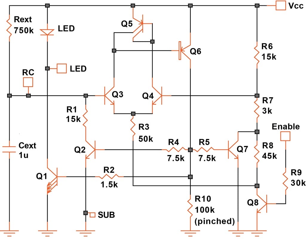
Figure 13-15. Circuit generating brief current pulses. [click to enlarge]
Q3 and Q4 form a simple comparator, with Q5 as an active load. Rext charges Cext. Q6, Q2, and Q7 turn ON when the voltage at the base of Q3 exceeds that at the base of Q4. Through the voltage divider R6/R7/R8, Q7 now abruptly lowers the potential at the base of Q4, while Q2 discharges Cext through R1.
When the voltage across the capacitor drops to the new level at the base of Q4, Q6 turns OFF and the cycle starts anew.
The frequency (1 Hz, in this case) is set by Rext and Cext. The pulse width (20 ms) is set by R1 and Cext. Not counting the variation of the external components, the frequency is accurate to within 2% from 3 to 5.5 V. However, the pulse width shown in Figure 13-16 reflects the variation of R1, a diffused resistor.
LEDs have a rather large forward voltage drop (about 2 V), so a supply voltage of at least 2.5 V is required. Figure 13-16 shows the voltage at node RC and the current through the LED (40 mA).
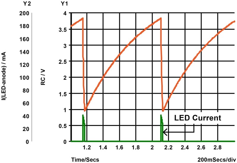
Figure 13-16. Waveforms of the pulse generator.
The LED current is primarily determined by the size of Q1—it operates in the high-current region, where the gain has already decreased, but the spread of hFE becomes narrow. The average current consumption is 1 mA.
CMOS Pulse Generator
It’s interesting to also consider a CMOS design for the same function. Figure 13-17 provides an example.
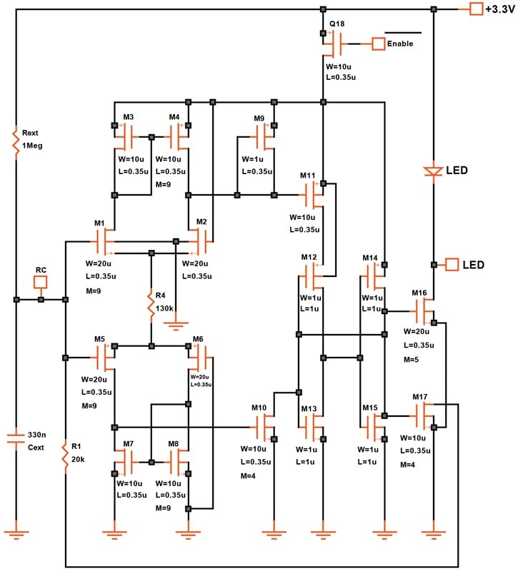
Figure 13-17. CMOS design for a pulse generator. [click to enlarge]
We can avoid using a resistive divider (and thus save current) by using two comparators and making two of the transistors in each comparator nine times the size of the others. This results in an offset of some 200 mV.
The reference potentials for the comparators are the supply lines. As the voltage across the external capacitor rises to 200 mV below the positive supply, the upper comparator (M1 to M4) sets the flip-flop (M12 to M15). As it falls to 200 mV above ground, the lower comparator resets the flip-flop. The capacitor voltage is illustrated in Figure 13-18.
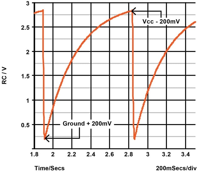
Figure 13-18. Voltage at the RC node of the CMOS pulse generator.
Cext is charged by Rext (1 second) and discharged by R1 (20 ms). The two times are surprisingly accurate, exhibiting a 3% change from 3.0 to 3.6 V and 0 to 100 °C.
The output current, on the other hand, shows the weakness of CMOS. It varies ±21% with a supply voltage change of ±10%. For this reason, we may need to use an even larger output transistor (M16) and a resistor in series with the LED.
With a 20 ms pulse of 37 mA every second, the entire circuit consumes just 650 μA average.
CMOS Timer Circuit
Figure 13-19 provides a second example—a timer, this time. It draws 1 μA at 1.8 V, showing just how low a power dissipation we can achieve by avoiding a resistor divider.
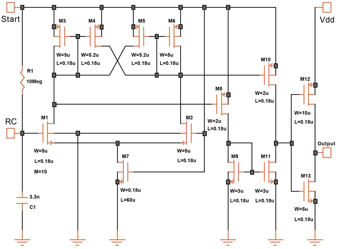
Figure 13-19. A 1.8 V timer that consumes just 1 μA. [click to enlarge]
Except for the output converter, the entire circuit is powered from the Start pulse, which rises from ground to Vdd. The logic input must stay high longer than the set timing.
Alternatively, the Start terminal can simply be connected to Vdd. The circuit then becomes a start-up timer..
M1 to M6 form a comparator. By making M1 ten times as wide as M2, an 80 mV offset is created. Because the gate of M2 is connected to Vdd, the comparator switches at 80 mV below Vdd. The voltage across the capacitor and the comparator output are shown in Figure 13-20.
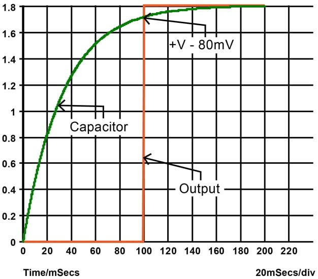
Figure 13-20. Switching threshold of the 1.8 V timer.
The switching action is enhanced by employing a small amount of positive feedback. We get this because M4 and M5 are slightly wider than M3 and M6 and deliver their drain currents to the opposite sides (see also the CMOS comparator with hysteresis).
The operating current for the comparator is provided by a long, thin transistor (M7). The advantage of such a device is that it produces about 0.6 μA using a relatively small area. A resistor doing the same job (1.2 MΩ) would be painfully large.
On the other hand, an MOS transistor with its gate connected to the supply is hardly a constant current source. With a 25% change in supply (1.6 to 2.0 V) the current changes by 70% (0.50 to 0.85 μA). Here, we can afford to live with this shortcoming.
The two outputs of the comparator are level-shifted by M8, M10, and the active load M9/M11 to fit the input of an inverter.
A circuit operating at such a low current is, of course, quite slow—a significant timing error occurs below about 50 μs (20 kHz). At lower speeds, you can expect an accuracy of better than ±5% from 1.6 to 2.0 V and 0 to 100 °C.