Facebook
 Google
 GitHub
 Linkedin
The RF Engineer’s Guide to the Decibel
RF engineering, like all scientific disciplines and subdisciplines, involves quite a bit of specialized terminology. One of the most important words that you will need when working in the world of RF is “dB” (and some variants thereof). If you become deeply entrenched in an RF project, you may find that the word “dB” becomes as familiar to you as your own name.
As you probably know, dB stands for decibel. It’s a logarithmic unit that provides a convenient way of referring to ratios, such as the ratio between the amplitudes of an input signal and an output signal.
We won’t cover the generic details of decibels because they are already available on this page of the AAC Electric Circuits textbook. Instead, we will focus on practical aspects of the decibel in the specific context of RF systems.
Relative, Not Absolute
It is easy to forget that dB is a relative unit. You cannot say, “The output power is 10 dB.”
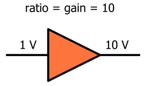
Voltage is an absolute measurement because we always speak of a potential difference, i.e., the difference in potential between two points; usually we are referring to the potential of one node with respect to a 0 V ground node. Current is also an absolute measurement because the unit (amperes) involves a specific amount of charge with respect to a specific amount of time. In contrast, dB is a unit that involves the logarithm of a ratio between two numbers. A straightforward example is amplifier gain: If the power of the input signal is 1 W and the power of the output signal is 5 W, we have a ratio of 5:
$$10\log_{10}\left(\frac{P_{OUT}}{P_{IN}}\right)=10\log_{10}\left(5\right)\approx7\ dB$$
Thus, this amplifier provides 7 dB of power gain—i.e., the ratio between the output signal strength and the input signal strength can be expressed as 7 dB.
Why dB?
It would certainly be possible to design and test RF systems without the use of dB, but in practice dB’s are everywhere. One advantage is that the dB scale allows us to express very large ratios without using very large numbers: a power gain of 1,000,000 is only 60 dB. Also, the total gain or loss of a signal chain is easily computed in the dB domain, because the individual dB figures are simply added (whereas multiplication would be required if we were working with ordinary ratios).
Another advantage is something that we’re familiar with from our experience with filters. RF systems revolve around frequencies and the various ways in which frequencies are generated, controlled, or affected by components and parasitic circuit elements. The dB scale is convenient in a context such as this because frequency response plots are intuitive and visually informative when the frequency axis uses a logarithmic scale and the amplitude axis uses a dB scale.
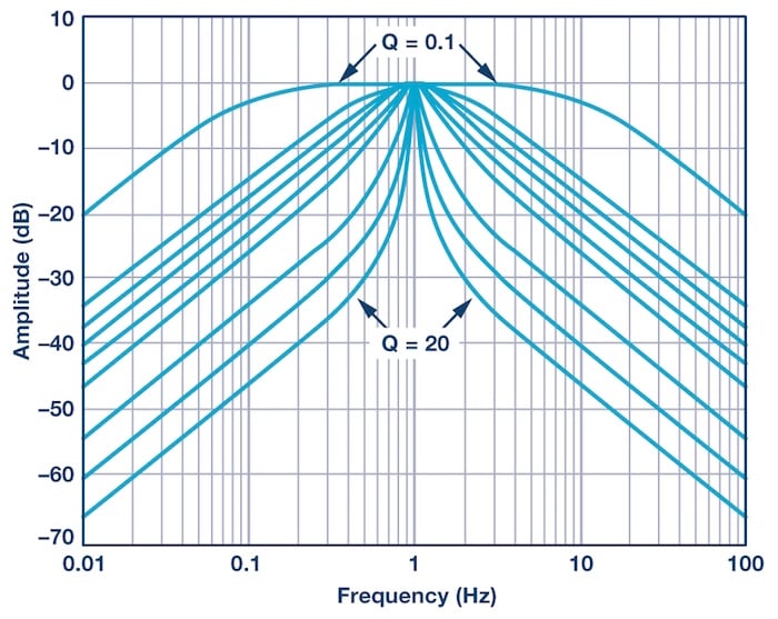
A Bode plot showing the magnitude response of different band-pass filters. Image courtesy of AnalogDialogue.
When dB Is Absolute
We’ve established that dB is a ratio and thus cannot describe the absolute power or amplitude of a signal. However, it would be awkward to be constantly switching back and forth between dB and non-dB values, and perhaps this is why RF engineers developed the dBm unit.
We can avoid the “ratios only” problem by simply creating a new unit that always includes a reference value. In the case of dBm, the reference value is 1 mW. Thus, if we have a 5 mW signal and we want to stay within the realm of dB, we can describe this signal as having a power of 7 dBm:
$$10\log_{10}\left(\frac{5\ mW}{1\ mW}\right)=10\log_{10}\left(5\right)\approx7\ dBm$$
You definitely want to familiarize yourself with the concept of dBm. This is a standard unit used in real-life RF system development, and it’s very convenient when, for example, you are calculating a link budget, because gains and losses expressed in dB can simply be added to or subtracted from the output power expressed in dBm.
There is also a dBW unit; this uses 1 W for the reference value instead of 1 mW. Nowadays most RF engineers are working with relatively low-power systems, and this probably explains why dBm is more common.
More dB Variants
Two other dB-based units are dBc and dBi.
Instead of a fixed value such as 1 mW, dBc uses the strength of the carrier signal as the reference. For example, phase noise (discussed in page 2 of this chapter) is reported in units of dBc/Hz; the first part of this unit indicates that the phase noise power at a specific frequency is being measured with respect to the power of the carrier (in this case “carrier” refers to the signal strength at the nominal frequency).
An idealized point-source antenna receives a certain amount of energy from the transmitter circuit and radiates it equally in all directions. These “isotropic” antennas are considered to have zero gain and zero loss.
Other antennas, however, can be designed to concentrate radiated energy in certain directions, and in this sense an antenna can have “gain.” The antenna is not actually adding power to the signal, but it effectively increases the transmitted power by concentrating electromagnetic radiation according to the orientation of the communication system (obviously this is more practical when the antenna designer knows the spatial relationship between the transmitter and receiver).
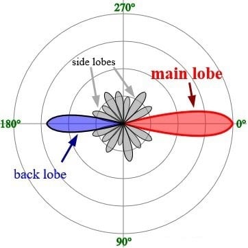
Image from Timothy Truckle (own work) [GFDL]. Here you can see the unequal distribution of radiated energy that results in gain in the forward direction (i.e., 0°).
The dBi unit allows antenna manufacturers to specify a “gain” figure that uses the ever-popular dB scale. As always, we need a ratio when we’re working with dB, and in the case of dBi, the antenna gain is given with reference to the gain of an isotropic antenna.
Some antennas (such as those accompanied by a parabolic dish) have significant amounts of gain, and thus they can make a nontrivial contribution to the range or performance of an RF system.
Summary
- The dB scale is a method of expressing ratios between two quantities. It is convenient and widely used in the context of RF design and testing.
- Though dB figures are inherently relative, absolute quantities can be expressed via the dB scale by using units that incorporate a standardized reference value.
- The most common absolute dB unit is dBm; it conveys the dB power of a signal with respect to 1 mW.
- The dBc unit expresses power with respect to the power of a related signal.
- The dBi unit expresses the gain of an antenna relative to the response of an idealized point-source antenna.