Facebook
 Google
 GitHub
 Linkedin
Basic Electricity
Basic Voltmeter Use
12 questions By Tony R. Kuphaldt
-
Question 4 of 12
Many electronic circuits use what is called a split or a dual power supply:

Determine what a digital voltmeter would indicate if connected between the following points:
- • Red lead on Ä”, black lead on ground
- • Red lead on “B”, black lead on ground
- • Red lead on Ä”, black lead on “B”
- • Red lead on “B”, black lead on Ä”
NOTE: in electronic systems, “ground” is often not associated with an actual earth-soil contact. It usually only refers to a common point of reference somewhere in the circuit used to take voltage measurements. This allows us to specify voltages at single points in the circuit, with the implication that “ground” is the
other point for the voltmeter to connect to.
Reveal answer- • Red lead on “A”, black lead on ground (Digital voltmeter reads 15 volts)
- • Red lead on “B”, black lead on ground (Digital voltmeter reads -15 volts)
- • Red lead on “A”, black lead on “B” (Digital voltmeter reads 30 volts)
- • Red lead on “B”, black lead on Ä” (Digital voltmeter reads -30 volts)
Notes:This question may be easily answered with only a voltmeter, two batteries, and a single “jumper” wire to connect the two batteries in series. It does not matter if the batteries are 15 volts each! The fundamental principle may still be investigated with batteries of any voltage, so this is a very easy demonstration to set up during discussion time.
-
Question 5 of 12
Determine how much voltage a voltmeter would indicate when connected between the following points in this circuit:
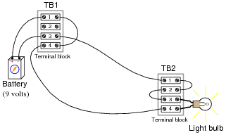
- • Between TB1-1 and TB1-3
- • Between TB1-4 and TB2-4
- • Between TB2-3 and TB2-1
- • Between TB1-1 and TB2-1
Hint: it might help to draw a neat schematic diagram of this circuit first, with all connection points labeled!
Reveal answer- • Between TB1-1 and TB1-3 (Voltmeter measures 9 volts)
- • Between TB1-4 and TB2-4 (Voltmeter measures 0 volts)
- • Between TB2-3 and TB2-1 (Voltmeter measures 0 volts)
- • Between TB1-1 and TB2-1 (Voltmeter measures 9 volts)
Notes:This question provides an opportunity to discuss the concept of electrically common points: namely, that there can be no substantial voltage built up between points that are made “electrically common” by means of low-resistance connections between them.
This is also an opportunity to develop the skill of drawing a schematic diagram for a real-life circuit. Schematic diagrams, of course, are very helpful in that they provide a nice, neat layout of all circuit components, making visualization of voltage drops and other quantities easier.
-
Question 6 of 12
Determine how much voltage a voltmeter would indicate when connected between the following points in this faulted circuit:

- • Between TB1-1 and TB1-3
- • Between TB1-4 and TB2-4
- • Between TB2-3 and TB2-1
- • Between TB1-1 and TB2-1
Hint: it might help to draw a neat schematic diagram of this circuit first, with all connection points labeled!
Reveal answer- • Between TB1-1 and TB1-3 (Voltmeter measures 9 volts)
- • Between TB1-4 and TB2-4 (Voltmeter measures 9 volts)
- • Between TB2-3 and TB2-1 (Voltmeter measures 0 volts)
- • Between TB1-1 and TB2-1 (Voltmeter measures 9 volts)
Notes:Ask your students this question: how does the break in the wire affect electrical “commonality” between TB1-4 and TB2-4?