Facebook
 Google
 GitHub
 Linkedin
Basic Electricity
Basic Voltmeter Use
12 questions By Tony R. Kuphaldt
-
Question 7 of 12
Determine what these four voltmeters (A, B, C, D) will register when connected to this circuit in the following positions (assume a battery voltage of 6 volts):
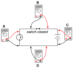
- • Voltmeter A =
- • Voltmeter B =
- • Voltmeter C =
- • Voltmeter D =
Reveal answer- • Voltmeter A = 6 volts
- • Voltmeter B = 0 volts
- • Voltmeter C = 6 volts
- • Voltmeter D = 0 volts
Notes:Students often find the terms “open” and “closed” to be confusing with reference to electrical switches, because they sound opposite to the function of a door (i.e. you can only go through an open door, but electricity can only go through a closed switch!). The words actually make sense, though, if you look at the schematic symbol for an electrical switch as a door mounted “sideways” in the circuit. At least visually, then, “open” and “closed” will have common references.
One analogy to use for the switch’s function that makes sense with the schematic is a drawbridge: when the bridge is down (closed), cars may cross; when the bridge is up (open), cars cannot.
I have found that the concept of electrically common points is most helpful when students first learn to relate voltage drop with continuity (breaks or non-breaks) in a circuit.
To be able to immediately relate the expected voltage drop between two points with the electrical continuity between those points is a very important foundational skill in electrical troubleshooting. Without mastery of this skill, students will have great difficulty detecting and correcting faults in circuits caused by poor connections and broken wires, which constitute a fair portion of realistic circuit failures.
-
Question 8 of 12
Determine what these four voltmeters (A, B, C, D) will register when connected to this circuit in the following positions (assume a battery voltage of 6 volts):
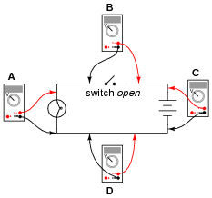
- • Voltmeter A =
- • Voltmeter B =
- • Voltmeter C =
- • Voltmeter D =
Reveal answer- • Voltmeter A = 0 volts
- • Voltmeter B = 6 volts
- • Voltmeter C = 6 volts
- • Voltmeter D = 0 volts
Notes:Students often find the terms “open” and “closed” to be confusing with reference to electrical switches, because they sound opposite to the function of a door (i.e. you can only go through an open door, but electricity can only go through a closed switch!). The words actually make sense, though, if you look at the schematic symbol for an electrical switch as a door mounted “sideways” in the circuit. At least visually, then, “open” and “closed” will have common references.
One analogy to use for the switch’s function that makes sense with the schematic is a drawbridge: when the bridge is down (closed), cars may cross; when the bridge is up (open), cars cannot.
I have found that the concept of electrically common points is most helpful when students first learn to relate voltage drop with continuity (breaks or non-breaks) in a circuit.
To be able to immediately relate the expected voltage drop between two points with the electrical continuity between those points is a very important foundational skill in electrical troubleshooting. Without mastery of this skill, students will have great difficulty detecting and correcting faults in circuits caused by poor connections and broken wires, which constitute a fair portion of realistic circuit failures.
-
Question 9 of 12
Shown here is a circuit constructed on a PCB (a “Printed Circuit Board”), with copper “traces” serving as wires to connect the components together:
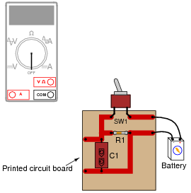
How would the multimeter be used to measure the voltage across the component labeled “R1” when energized? Include these important points in your answer:
- • The configuration of the multimeter (selector switch position, test lead jacks)
- • The connections of the meter test leads to the circuit
- • The state of the switch on the PCB (open or closed)
Reveal answer
The test lead connections (to the circuit) shown are not the only correct answer. It is possible to touch the test leads to different points on the PCB and still measure the voltage across the resistor (component labeled R1). What are some alternative points on the PCB where the voltage across R1 could be measured?
Notes:Many multimeters use “international” symbols to label DC and AC selector switch positions. It is important for students to understand what these symbols mean.
The test lead connections (to the circuit) shown are not the only correct answer. It is possible to touch the test leads to different points on the PCB and still measure the voltage across the resistor (R1). However, if there are poor connections on the circuit board (between component leads and copper traces), measuring voltage at points on the circuit board other than directly across the component in question may give misleading measurements. Discuss this with your students.