Facebook
 Google
 GitHub
 Linkedin
Basic Electricity
Elementary Circuits
12 questions By Tony R. Kuphaldt
-
Question 10 of 12
Examine this schematic diagram:

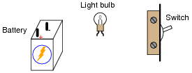
Now, without moving the following components, show how they may be connected together with wires to form the same circuit depicted in the schematic diagram above:
Reveal answer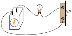
Follow-up question: suppose the circuit were built like this but the light bulb did not turn on when the switch was closed. Identify at least five specific things that could be wrong with the circuit to cause the light not to turn on when it should.
Notes:One of the more difficult skills for students to develop is the ability to translate a nice, neat schematic diagram into a messy, real-world circuit, and visa-versa. Developing this skill requires lots of practice.
In case students have not learned battery symbol convention yet, please point out to them the “ ” and “-” polarity marks, and note which side of the battery is which.
One analogy to use for the switch’s function that makes sense with the schematic is a drawbridge: when the bridge is down (closed), cars may cross; when the bridge is up (open), cars cannot.
-
Question 11 of 12

This circuit has four “test points” labeled with the letters A, B, C, and D. Assuming the circuit is functioning (light bulb is energized), determine whether or not there will be substantial voltage between the following sets of points:
- • Between A and B: voltage or no voltage?
- • Between B and C: voltage or no voltage?
- • Between C and D: voltage or no voltage?
- • Between D and A: voltage or no voltage?
- • Between A and C: voltage or no voltage?
- • Between D and B: voltage or no voltage?
Based on these voltage determinations, what general statement(s) can you make about the presence or absence of voltage in a functioning circuit?
Reveal answerRather than tell you whether or not there will be voltage, I’ll let you build your own circuit and measure for yourself! I will, however, give you two “rules” that may be derived from these measurements:
- • Measuring between two terminals of a voltage source, or between two terminals of an energized load (a component having substantial resistance, with current going through it), there will be a voltage.
- • Measuring between two points that are electrically common to each other, there will be no voltage (or at least an insignificant amount of voltage).
Notes:Electrically common points are defined as points within a circuit that are connected together by conductors of negligible resistance.
The concept of “electrically common” points is one that I have found very helpful in the analysis of circuits, because there are a some simple rules regarding voltage that relate to whether or not points in a circuit are “common” to each other.
-
Question 12 of 12
In this electrical circuit, trace the direction of current through the wires:
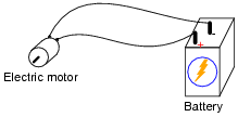
Reveal answerThis is a “trick” question, as there are two accepted ways of denoting the direction of electric current: conventional flow (sometimes called hole flow), and electron flow. Here’s more about electron versus conventional flow.
Notes:This question breaches one of the more contentious subjects in electricity/electronics: which way do we denote the direction of current? While there is no debate as to which direction electrons move through a metal conductor carrying current, there are two different conventions for denoting current travel, one of which goes in the direction of electrons and the other which goes against the direction of electrons. The reason for having these two disparate conventions is embedded in the history of electrical science, and what your students find in their research will likely fuel an interesting conversation.