Facebook
 Google
 GitHub
 Linkedin
Mathematics for Electronics
Phasor Mathematics
13 questions By Tony R. Kuphaldt
-
Question 10 of 13
Electrical engineers usually express the frequency of an AC circuit in terms of angular velocity, measured in units of radians per second rather than cycles per second (Hertz, or Hz).
First, explain what a radian is. Next, write an equation relating frequency (f) in Hertz to angular velocity (ω) in radians per second. Hint: the relationship between the two is perhaps most easily understood in terms of a two-pole AC generator, or alternator, where each revolution of the rotor generates one full cycle of AC.
Reveal answerA radian is that angle describing a sector of a circle, whose arc length is equal to the radius of the circle:

Next, the equivalence between angular velocity (ω) and frequency (f):
ω = 2 πf Notes:Personally, I find the rotating alternator model the best way to comprehend the relationship between angular velocity and frequency. If each turn of the rotor is one cycle (2 π radians), and frequency is cycles per second, then one revolution per second will be 1 Hertz, which will be 2 π radians per second.
-
Question 11 of 13
Suppose we have a simple two-pole AC generator, or alternator, the two stator windings on either side of the rotor connected together so as to function as a single winding:
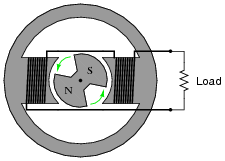
Ideally, this machine will generate a sinusoidal output voltage as the rotor turns. Suppose now that we write index marks on the rotor shaft to measure its position as it turns, and we represent that position with the Greek letter “Theta” (Θ). It is purely arbitrary where we label the “zero” position on the shaft, so we choose to mark that point at some easily-identified point on the output waveform: the place where the coil output voltage peaks positive while rotating counter-clockwise. When spun, the instantaneous output voltage will then match the cosine function. In other words, the instantaneous output voltage will be proportional to the cosine of the shaft angle:
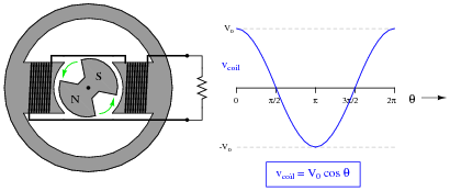
We may represent the coil’s voltage with the equation vcoil = V0 cosΘ. If we precisely know the peak voltage value (V0) and the shaft position (Θ), we may precisely predict the coil voltage at any instant in time (vcoil).
However, there is a more complete way of describing what is happening in this alternator. The equation vcoil = V0 cosΘ is adequate for predicting coil voltage from shaft position, but it is not adequate for doing the reverse: predicting shaft position from coil voltage. Note that there are only two points on the voltage waveform where a voltage value corresponds to a unique shaft position, and those points are the positive and negative peaks. At any other value of instantaneous voltage (−V0
< vcoil < V
0), there are multiple possible shaft positions. The most obvious example of this is where vcoil = 0. Here, the shaft position could be [(π)/2] radians, or it could be [(3 π)/2] radians. Note that we consider the positive peak to occur at only one position (0 radians) and not two positions (0 and 2 π radians) in one revolution because 2 π radians is identical to 0 radians just as 360 degrees is equivalent to 0 degrees.
In order to uniquely describe the alternator’s shaft position in terms of output voltage, we need more information than just the instantaneous voltage at one coil. What we need is another coil, an imaginary coil, shifted in angular position from the first coil:
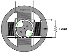
Like the first coil (the real coil), the imaginary coil’s output voltage will also be sinusoidal. However, it will generate an output voltage at a different phase than the real coil’s output voltage.
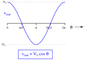
Plot the waveform of the imaginary coil’s voltage, superimposed on the waveform of the real coil’s output voltage, and then write an equation expressing both instantaneous voltages as a complex sum: the real coil’s voltage as a real number and the imaginary coil’s voltage as an imaginary number (complete with the j prefix). Then, use Euler’s relation to re-write this complex sum as a complex exponential expression.
Reveal answer
Alternator output as a complex sum:
Vout = V0 cosΘ + j V0 sinΘ Alternator output as a complex exponential:
Vout = V0 ej Θ Notes:Here, I tried my best to give simple, real-world meaning to phasor notation. Interestingly, the oft-lamented label of “imaginary” actually works to my advantage, describing the output of a coil that has no useful purpose but to define the alternator’s shaft position in terms of a quadrature voltage.
-
Question 12 of 13
∫f(x) dx Calculus alert!
Impedance is defined as the complex ratio of voltage and current:Z = V IWe may determine the complex definition of impedance provided by an inductor if we consider the equation relating inductor voltage and inductor current:
v = L d dt[ i(t) ] First, substitute a phasor expression of current into the above equation, then differentiate with respect to time to obtain an expression for voltage:
i(t) = ej ωt v = L d dt[ ej ωt ] Then, divide the two phasor expressions to obtain an expression for inductive impedance.
Reveal answerZL = j ωL Follow-up question: explain why the following expression for inductive impedance is equivalent to the one shown above:
ZL = ωL ej π/ 2 Notes:In order to solve this problem, your students must remember the basic rule for differentiating exponential functions:
d dx[ eax ] = a eax This is one of the beauties of representing sinusoidal voltages and currents in complex exponential (phasor) form: it makes differentiation and integration relatively easy! In this sense, the Euler relation of ejx = cosx j sinx is a transform function, transforming one type of mathematical problem into a different (easier) type.